3 Functional description of the structure switches
3.4 Controller types (S1, S42 to S45)
Manual
SIPART DR21
C73000-B7476-C143-08
89
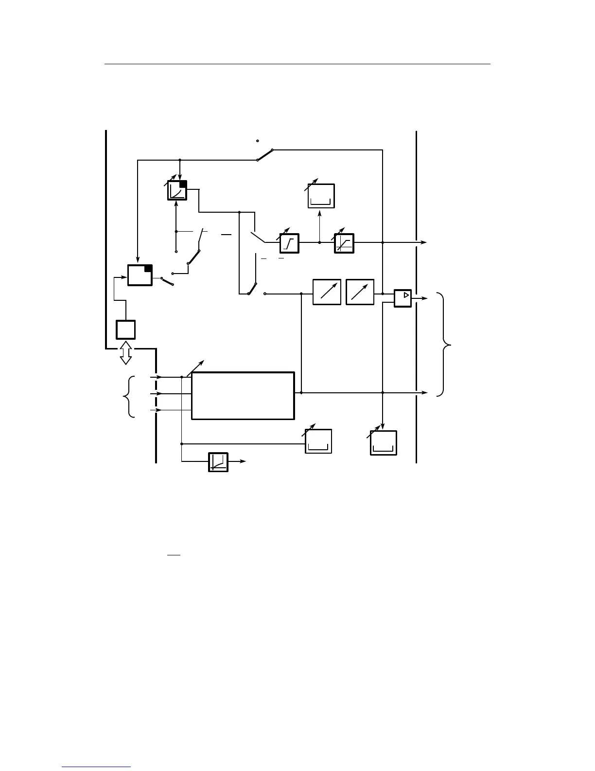
3.4.7 Fixed setpoint controller with one setpoint (control system coupling)
(S1 = 5)
1)
tF
0
0
c1, c2, c3
x
1
S45
SA,SE
1
S43
Factory setting
c1=c2=c3=0
x=x1+c1· (x2-c2 · x3+c3)
x2
x1
x3
xd
x
II, IV
W
A
Adaptation
tS
wi1
n
o
x1
w
0/1
2...5
2/4 0/1/3
S51
1)
as of software version --A5
I
w1
ES
SES
S85
Int∨
CB
A
A
=H∨N∨Si
H=Hi∨He
0000
X
W
+
--
x
III
0000
0000
Figure
3-29,
Page 1 10
Figure
3-21,
Page 92
Figure
3-1,
Page
49
Figure 3-19 Block diagram S1 = 5, fixed setpoint controller with one setpoint for control system coupling
This fixed setpoint controller is designed specially for coupling to the control system. The con-
trol interventions by signals Int and CB are available for locking the control system operation via
SES. With Int∨CB
the setpoint signal wi
ES
is separated and manual intervention via He
ES
at
S51 = 3 is suppressed.
The other wiring of the input function is almost identical with the structure S1 = 0 (see chapter
3.4.2, page 59). (Due to the control system control possible at S1 = 5, only an internal setpoint
can be implemented here)
S51 = 3 is expressly recommended for this connection.