3 Functional description of the structure switches
3.4 Controller types (S1, S42 to S45)
Manual
88
SIPART DR21
C73000-B7476-C143-08
Control s igna ls
Message signals
Digital inputs Front Front Digital outputs
ove
0 y
S
3)
Safety operation
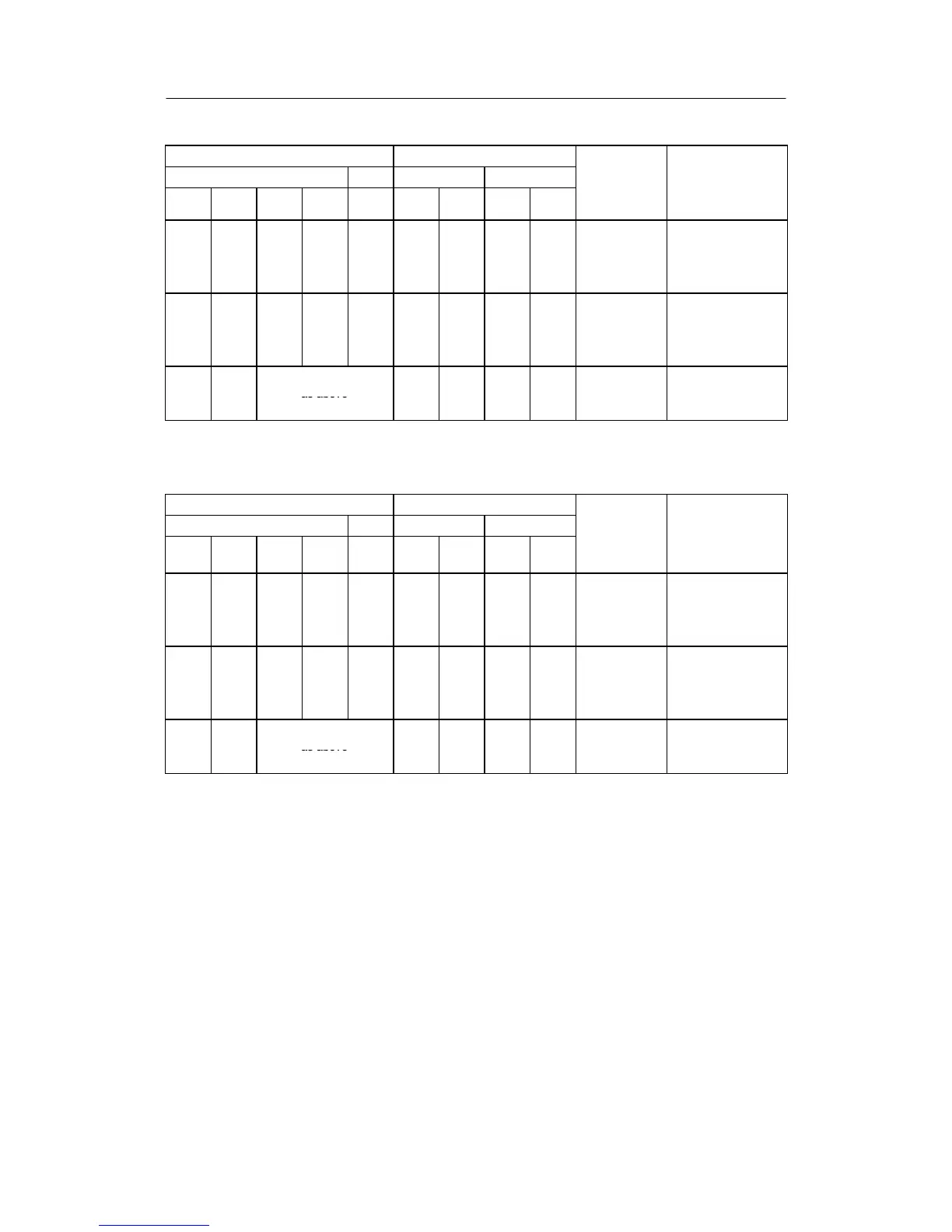
Table 3-13 Output switching manual control station S/K (S1 = 4)
Tracking operation has priority over manual operation (S49 = 0)
Control s igna ls Message signals
Digital inputs Front Front Digital outputs
ove
0 y
S
3)
Safety operation
1)
Source for y
E
at S85 = 0, 1, (4, 5 as of software version -A5), y is
N
as an absolute value assigned via S18. At S85 = 2,
3, y
ES
via the SES. The external manipulated variable through which SES (y
ES
) is fed in is tracked. When feeding in
via y
N
the feeding instrument must be tracked. At S-output with internal feedback, a y
E
-selection is not possible, here
the last y before switching is held.
2)
Blocking operation acts direction-dependently, changes to the opposite direction are possible.
3)
Function y
E
in S-controllers with internal feedback (S2 = 1) drive open- or closed otherwise parameterizable safety
setting value.
4)
0.9 flashing rhythm 0.1 off, 0.9 on
5) 0.5 = flashing rhythm 1:1
6) only if HiHe = 1
7) for S51
≠ 3,4
8) As of software version -A7 the signals He
DI
and He
ES
with S51 = 3, 4 have dynamic ef fect (0/1-edge). They then act
like the Hi-signal (see figure 3-3, page 53)
(n) tracking takes place to the value active before switching, therefore bumpless switching
↗ adjustable
Table 3-14 Output switching manual control station S/K (S1 = 4)
Manual operation has priority over tracking operation (S49 = 1)