3 Functional description of the structure switches
3.6 Controller output structures (S2, S49 to S55)
Manual
98
SIPART DR21
C73000-B7476-C143-08
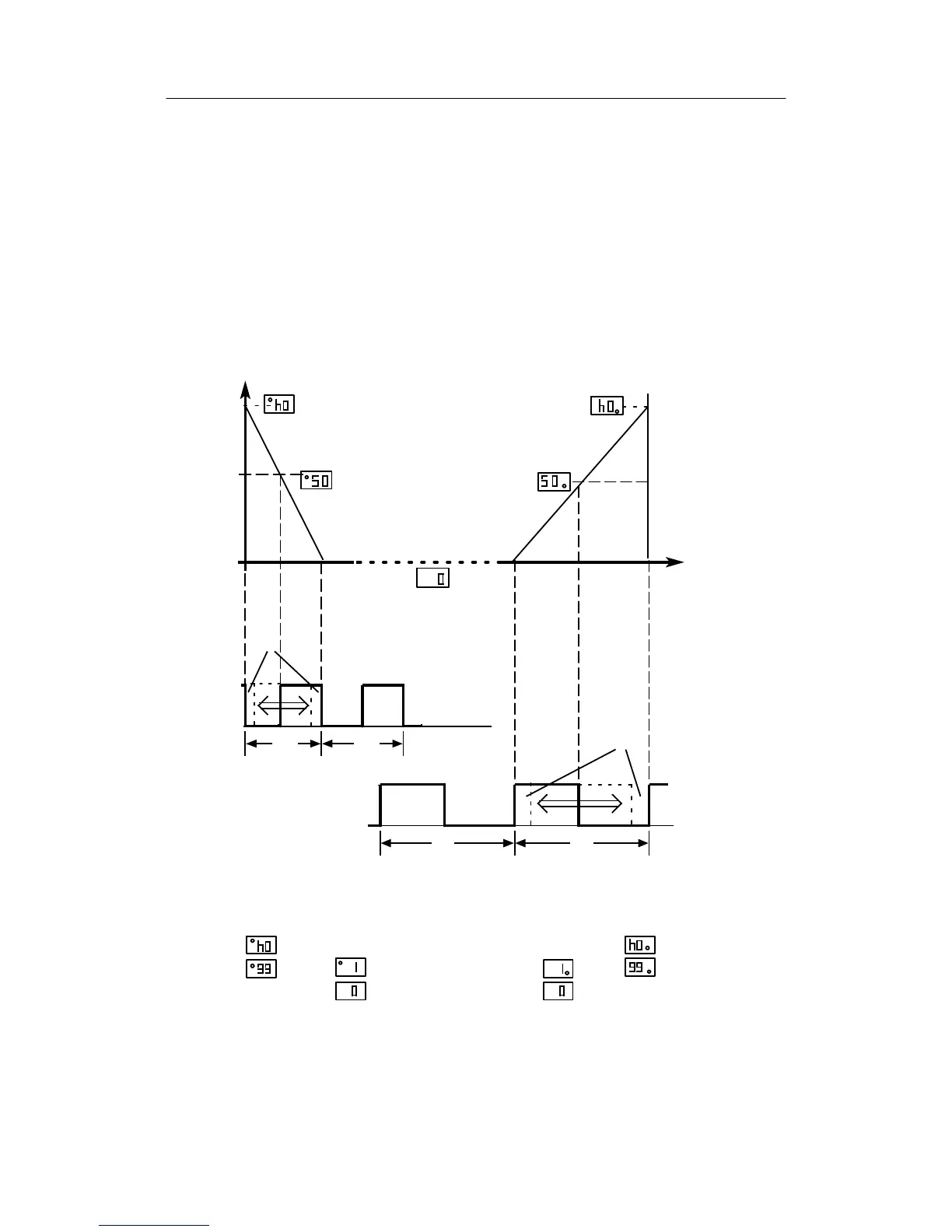
Y-display:
In switch position S54=2 the setting ranges heating/cooling are displayed with their setting
ratio [%]. Switching of the output stages is visible as a point in the display (10) and indicates
the setting range heating/cooling.
The ±Δy
-outputs can be assigned to the appropriate digital outputs with the structure switch
S57.
The analog output is assigned by the structure switch S56.
y=0toY1(cooling-Δy)
period duration tM from 0 to 1000 s
minimum pulse pause, -length: tA
y = Y2 to 100% (heating +Δy)
period duration tP from 0 to 1000s
minimum pulse pause, -length: tE
setting ratio
y
1
1
0,5
0,5
100 %
40%
0%
+
Δy
―Δy
Y1
Heating
35%
Y2
Chapter y = Y1 to Y2
Dead zone no setting pulses
tA
tE
On
Off
On
Off
tM tM
tP tP
Cooling, example
with setting ratio = 50 %
Heating, example
with setting ratio = 50 %
Cooling
y-display
Continuous contact
clocking
Dead zone, no output
Cooling
Heating
to
to
Figure 3-24 Setting ratio, actuating pulses of two-position controller