3 Functional description of the structure switches
3.4 Controller types (S1, S42 to S45)
Manual
90
SIPART DR21
C73000-B7476-C143-08
3.4.8 Slave controller without Int/Ext -switching (control system coupling)
(S1 = 6)
1)
tFI
c1, c3
x
SA,SE
Factory setting
c1=c3=0
x=x1+c1· x2+c3
S15, x1
xd
x
Adaptation
tS
x1
w
c4, c5
Factory setting
c4=1, c5=0
w
E
=c4·w
E
+c5
we
1)
as of software version --A5
S16, x2
II, IV
W
0000
Wx
+
--
S17
w
EA
III
0000
0000
I
x
Figure
3-29,
Page 1 10
Figure
3-21,
Page 92
Figure
3-1,
Page 49
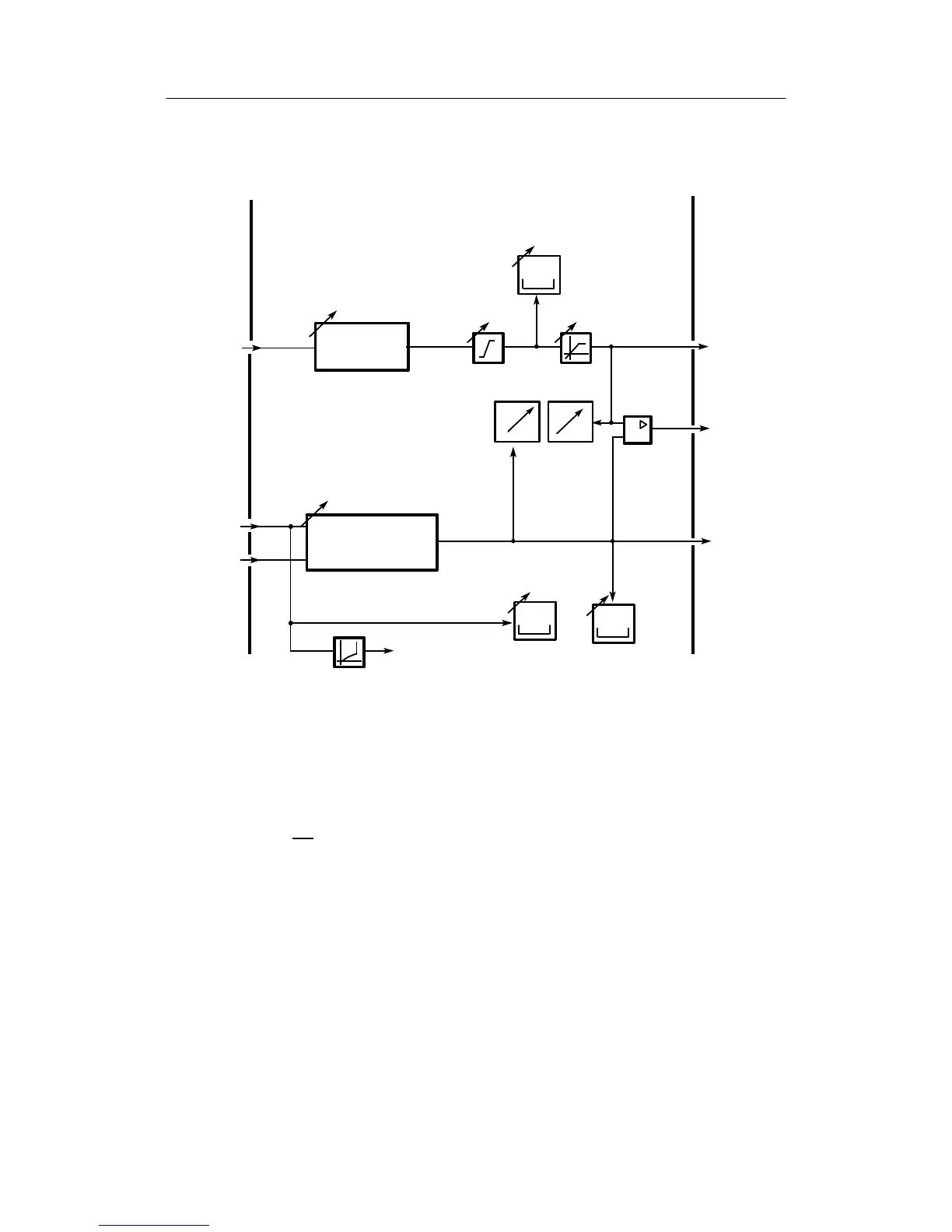
Figure 3-20 Block diagram S1 = 6, slave controller for control system coupling
This slave controller is designed specially for the control system coupling. It differs from the
structure S1 = 1 (see chapter 3.4.3, page 62) in that the setpoint switching to via Int and CB is
omitted and thus these control signals are available for locking the control system operation via
the SES. With Int∨CB
manual intervention via He
ES
at S51 = 3 is suppressed.
The other functions are unchanged in relation to S1 = 1. S51 = 3 is expressly recommended for
this connection.