3 Functional description of the structure switches
3.4 Controller types (S1, S42 to S45)
Manual
60
SIPART DR21
C73000-B7476-C143-08
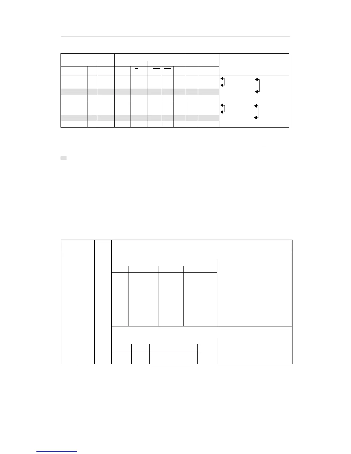
Control commands Alarm signals Active w
Digital inputs Front Front LED Digital outputs at S43= Explanations
H∨N∨Si CB
internal internal C RB RC 01
01000 00 wi1wi1(n)
1)
switchover switchover
00001 01 wi2wi2(n)with CB, Int=0 with Int,CB=1
01110 11
2)
wi2 wi2 (n)
00111 11 wi2wi2(n)
11000 00 wi1x
switchover switchover
10001 01 wi2x with CB,Int=0 with Int,CB=1
11110 11
2)
wi2 x
10111 11 wi2x
1)
tracking takes place at S45 = 0 and S43 = 1 to the control variable x, the tracking does not apply for switchover
wi1/wi2 at S45 = 1 automatic mode starts with wi=x (xd=0), the active setpoint runs to the old set value via the
possibly set setpoint ramp tS
2)
Factory setting fixed setpoint controller with 1 setpoint (S42 = 0: only Internal, Int = 1, S23 = 8: CB = 1) RB =Int
RC = Int∨
CB
Factory setting
Table 3-1 Switching between wi1 and wi2
With the Shift key (6) the digital x/w-display can be switched between the display levels I to
IV depending on the position of S81.
In display level II the active w can be displayed, in display level III the main control variable
x1. The inactive setpoint is displayed in the display level IV . The displayed active or inactive
setpoint can also be adjusted (see table 3-2).
The active setpoint- and actual value is displayed on the analog displays.
Structure
switches
Posi-
tion
Function
S81 Switching the w/x-digital display
Display order
I II III IV
[0] x/xv w/wv -- --
1 x/xv w/wv x1/xv --
2 x/xv w/wi1/wv -- wE/wvE/wi2
3 x/xv w/wi1/wv x1/xv wE/wvE/wi2
4 x/xv -- -- --
5 -- w/wv -- --
6 -- -- x1/xv --
7 xv wv x1 w
Identification of the displayed variables by the w- or x-signal lamp:
1 = steady light, 0.5 = flashing light, 0 = off
Display order
I II III IV
1 0 0.5 (0 at S81=6) 0 x-signal lamp
0 1 0 0,5 w-signal lamp
Table 3-2 Display levels (S81)