8 Maintenance
8.3 LED-test and software version
Manual
226
SIPART DR21
C73000-B7476-C143-08
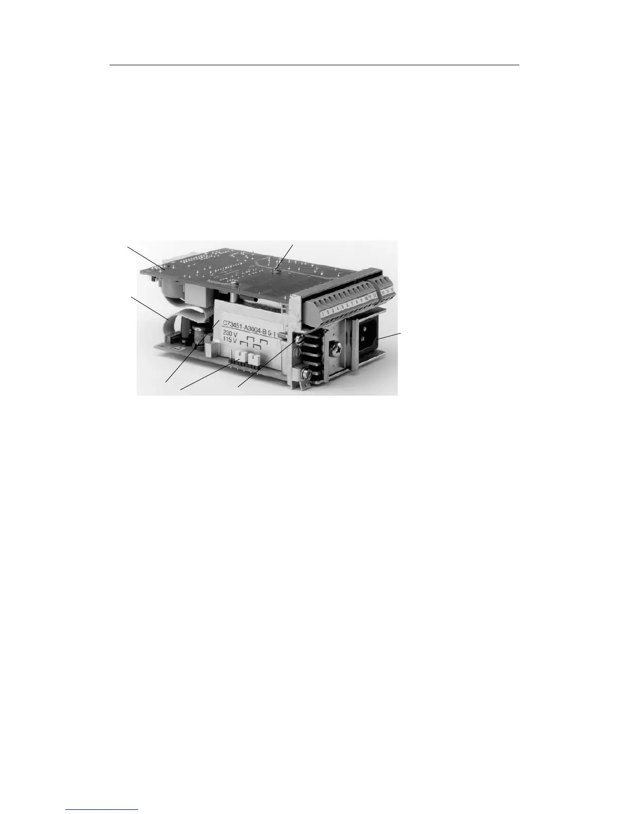
D Disconnect the power supply unit from the basic circuit board
(Components of the backplane module)
- Pull out the backplane module (see replacement of the backplane module)
- Pull out the ribbon cable plug (see (5) figue 8-3)
- Loosen the fastening screw of the basic circuit board (see (7) figure 8-3).
- Separate the basic circuit board and the power supply unit.
- Re-assemble in reverse order.
(Pay attention to correct plugging of jumpers (see (3) figure 8-3))
(1) Connecting plug
(2) Fastening screw for the
backplane module
(3) Plug--in jumpers
(4) Power supply unit
(5) Plug ribbon cable
(6) Basic circuit board
(7) Fastening screws for the
Basic circuit board
(7)
(6)
(5)
(4)
(3)
(2)
(1)
Figure 8-3 Backplane module
8.3 LED-test and software version
If the Shift key (6) is pressed for about 10 s (“PS” flashes on the manipulated variable display
after about 5 s), this leads to the LED-test. All LEDs light up, the displays show “8.8.8.8.” or
“88.” and a light marker covering 2 LEDs runs from 0 to 100% on both bargraphs (on reaching
100% it starts again at 0%).
If the Internal-/External key (16) is additionally pressed permanently during the lamp test, “dr21”
appears on the digital x/w-display and the controller software version on the digital y-display.
During the LED-test and display of the software version the controller continues to operate on-
line in its last operating mode.