7 Application examples for configuring the controller
7.2 Working with different setpoints
Manual
SIPART DR21
C73000-B7476-C143-08
195
7.2 Working with different setpoints
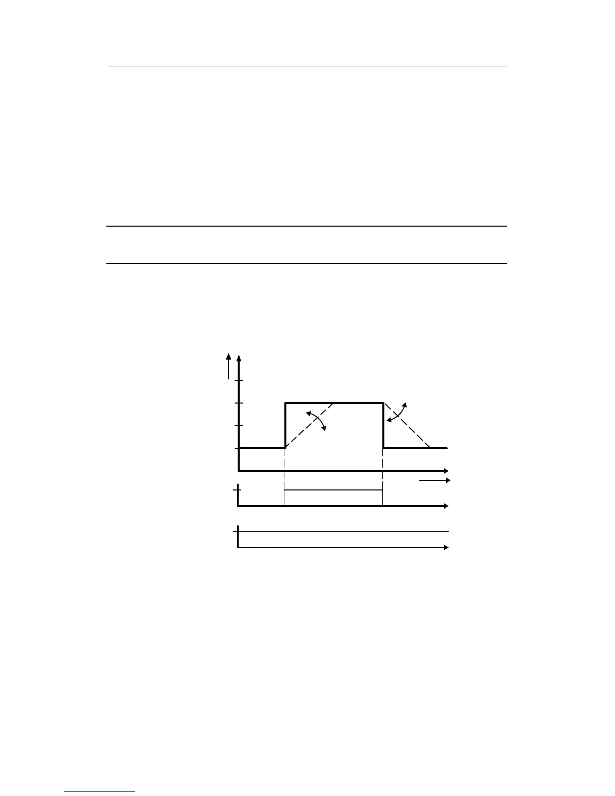
Function diagrams are shown on the following pages which illustrate on the time axis how set-
points change when
- the Internal/External key (16) on the front is pressed
- the structured functions of the digital input DI are triggered with logic 1 or logic 0.
The structure switches named next to the examples must be put in the specified positions for
the illustrated functions. Structure switches not listed are in the factory setting.
Example 1 two-setpoint operation as a fixed setpoint controller
(see chapter 3.4.2, page 59)
At S81 = 2/3 both setpoints can be called with the key (6) in the four-digit display (3) and then
adjusted with the keys (14), (15) on the front of the instrument. Switching from w1 to w2 takes
place with the Internal/External switch (16) (at CB = 1). The active setpoint is always shown on
the analog bargraph display (2). At S81 = 0/1/5 only the active setpoint can be shown on the
digital display.
w
i2
w
i1
t
0
w(%)
100
S1 = 0
S23= 8
S45 = 1
S42 = 2
S81 = 2
w
1
=w
i1
(can be set on the front)
w
2
=w
i2
(can be set on the front)
tS = setpoint ramp
Int
CB = 1 = High
Lo
Hi
tS
tS
Lo
Hi
Figure 7-1 Setpoint curve according to example 1