7 Application examples for configuring the controller
7.2 Working with different setpoints
Manual
SIPART DR21
C73000-B7476-C143-08
197
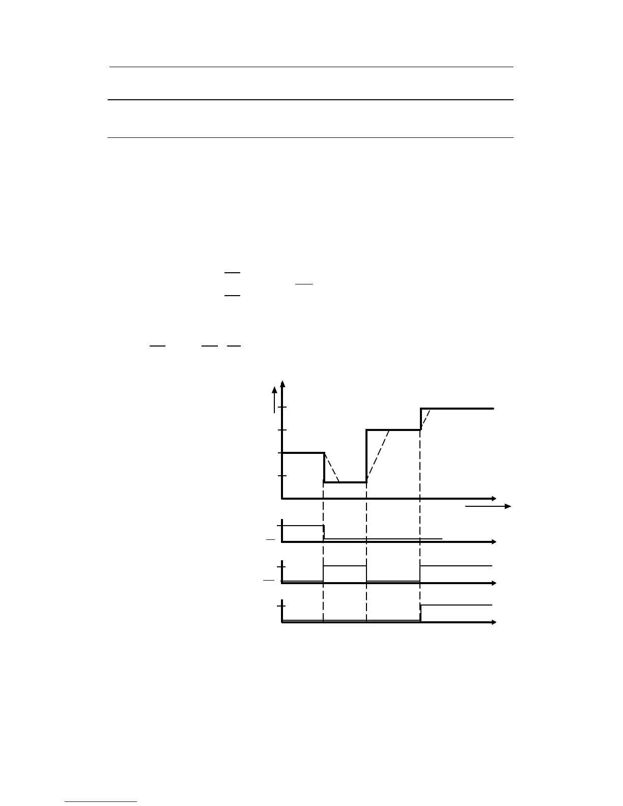
Example 3 Four-setpoint operation with one slave controller with Internal/
External switching and CB signal through the digital input
The analog input AI2/w
E
is overcontrolled to 0 or 100%:
wi setpoint which can be adjusted on the front
w
E
setpoint limit fixed by parameterization oFPA (setpoint limit start SA), w
E
over
controlledto0%.
SH safety setpoint set by parameterization.
w
E
setpoint limit fixed by parameterization oFPA (setpoint limit end SE)
w
E
overcontrolled to 100 %.
Switchings take place:
wi= key (16) to Internal
w
E
= key (16) to External (INT), CB signal High (CB). AI2 overcontrolled to 0% (SA)
SH= key (16) to External, CB from High to Low
(CB)
w
E
= key (16) to External (INT), CB signal High (CB). AI2 overcontrolled to 100% (SE)
Restriction of this circuit wi and SH must be within the limits SA to SE.
Also only the active setpoint can be displayed at S81 = 2/3. SH can only be reached by the
transition INT
∧CB to INT∧CB.
w
i
w
E
(SA)
SH
w
E
(SE)
t
0
w(%)
100
S1 = 1
wE on AI2 S17 = 2
CB on DI1 S23 = 1
S42 = 2
S43 = 0
S44 = 1
S45 = 1
Int/Ext key
100 %
DI1
AI2
Int
Int
CB
CB
0%
Attention!
SH (safety setpoint) can only
be selected based on w
E
(ex-
ternal setpoint).
Figure 7-3 Setpoint curve according to example 3