5 Operation
5.4 Configuration modes
Manual
SIPART DR21
C73000-B7476-C143-08
173
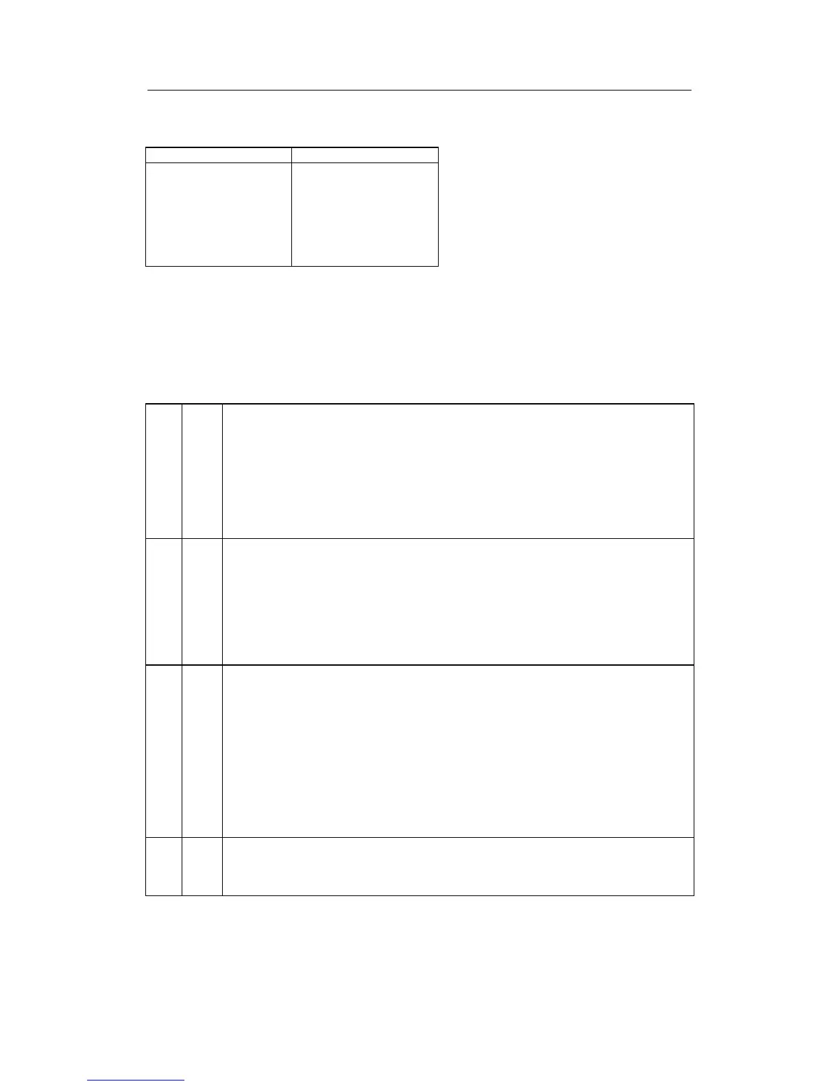
The serial interface in the DR21 must be set as follows for operation on the PROFIBUS-DP.
Structure switch Setting
S84
S85
S86
S87
S88
S89
S90
S91
1
2
0
0
0
0
3to125
0to9
5.4.6 Set UNI-module CAE3
The CAE3 menu is only offered in the selection mode if the structure switch S6 is set = 4 to 7
(input signal for AI3 is generated by the UNI-module)
With this menu the measuring range can be determined for the various signal transmitters
(selection with S8 and S9) and fine adjustment can be made.
S6 Input signal AI3 (slot 1) and transmitter fault message
[0] 0...20 mA or U,R,P,T without MUF
1 0...20 mA or U,R,P,T with MUF
2 4...20 mA or U without MUF
3 4...20 mA or U with MUF
4 UNI module Min at sensor break without MUF
5 UNI module Max at sensor break without MUF
6 UNI module Min at sensor break with MUF
7 UNI module Max at sensor break with MUF
S8 Input signal AI3 (slot 1) with UNI--module (only active at S6=4/5/6/7)
[0] mV (linear), with measuring range plug U or I
1 Thermocouple with internal reference point
2 Thermocouple with external reference point
3 PT100 4--wire connection
4 PT100 3--wire connection
5 PT100 2--wire connection
6 Resistance potentiometer with R < 600
7 Resistance potentiometer with 600 ≤ R<2.8k
S9 Thermocouple type AI3 (slot 1) with UNI--module (only active at S8=1/2)
[0] Type L
1 Type J
2 Type K
3 Type S
4 Type B
5 Type R
6 Type E
7 Type N
8 Type T
9 Type U
10 any type (without linearization)
S10 Temperature unit AI3 (slot 1) with UNI--module (only active at S8=1/2/3/4/5)
[0] Degrees Celsius
1 Degrees Fahrenheit
2 Kelvin
Table 5-6 Excerpt from the structure switch table