1 General Part -- Fundamental control technology terms Manual
12
SIPART DR21
C73000-B7476-C143-08
D Controller output signal
The controller ouptut signal must be adapted to the final control element. The following must
be used according to the type of drive/final control element:
Type of drive/actuator
Controller output signal
Electric actuators Three-position step controllers
Pneumatic and hydraulic actuators Continuous controllers
Direct heaters/coolers T wo-position controllers
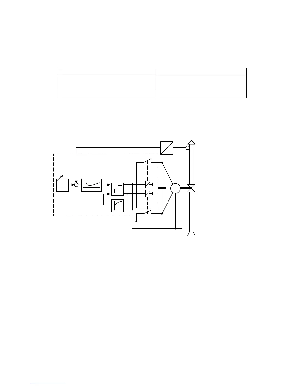
D Three-position step controller with internal feedback
The three-position step controller switches the electric motor of the actuator to clockwise,
stop or counterclockwise by means of relays or semiconductor switches. The rate of adjust-
ment of the actuator can be influenced using different switch-on/pause ratios.
w Command variable
x Controlled variable
xd System deviation
y Manipulated variable
1 Transmitter
2 Stepoint adjuster
3 Three-position switch
4 Feedback with time
response
5 Control amplifier
6 Actuator
2
M
w
xd
5
3
4
L1
N
1
x
6
y
0 to 20mA
(4 to 20mA)
Figure 1-7 Function diagram of three-position step controller
The output response to the three-position amplifier in conjunction with the integral-action
actuator permits a “continuous” manipulated variable taking into account the response
threshold.