3 Functional description of the structure switches
3.4 Controller types (S1, S42 to S45)
Manual
SIPART DR21
C73000-B7476-C143-08
87
S51
S54
2
1
S85
Y1
Y2
N
+yBL -yBL
oFF
2/3
0
2
0/1/(4/5)
1)
1
1
0
0
0
0
S55
S52
N
Si
yn
A
ya
tP, tM (S2 = 0)
YA
YE
YS
y
S56
-
Δy
S57
<>
S53
1/3
0/2
YA
YE
3
0
1
S2
tM, tA
tP, tE
+
Δy
S57
1/3
0/2
S53
S18
S29
S30
S19
Y
An
H
0/1
tM
2/3/(4/5)
1)
S85
1)
as of software version --A5
2)
as of software version --B2
1
y
R
y
H
y
N
y
ES
y
ES
y
E
y
HES
SES
00
12/13
10/11
0/1
S56
2)
Block diagram for S49 = 0, see controller output structures figure 3-28, page 105
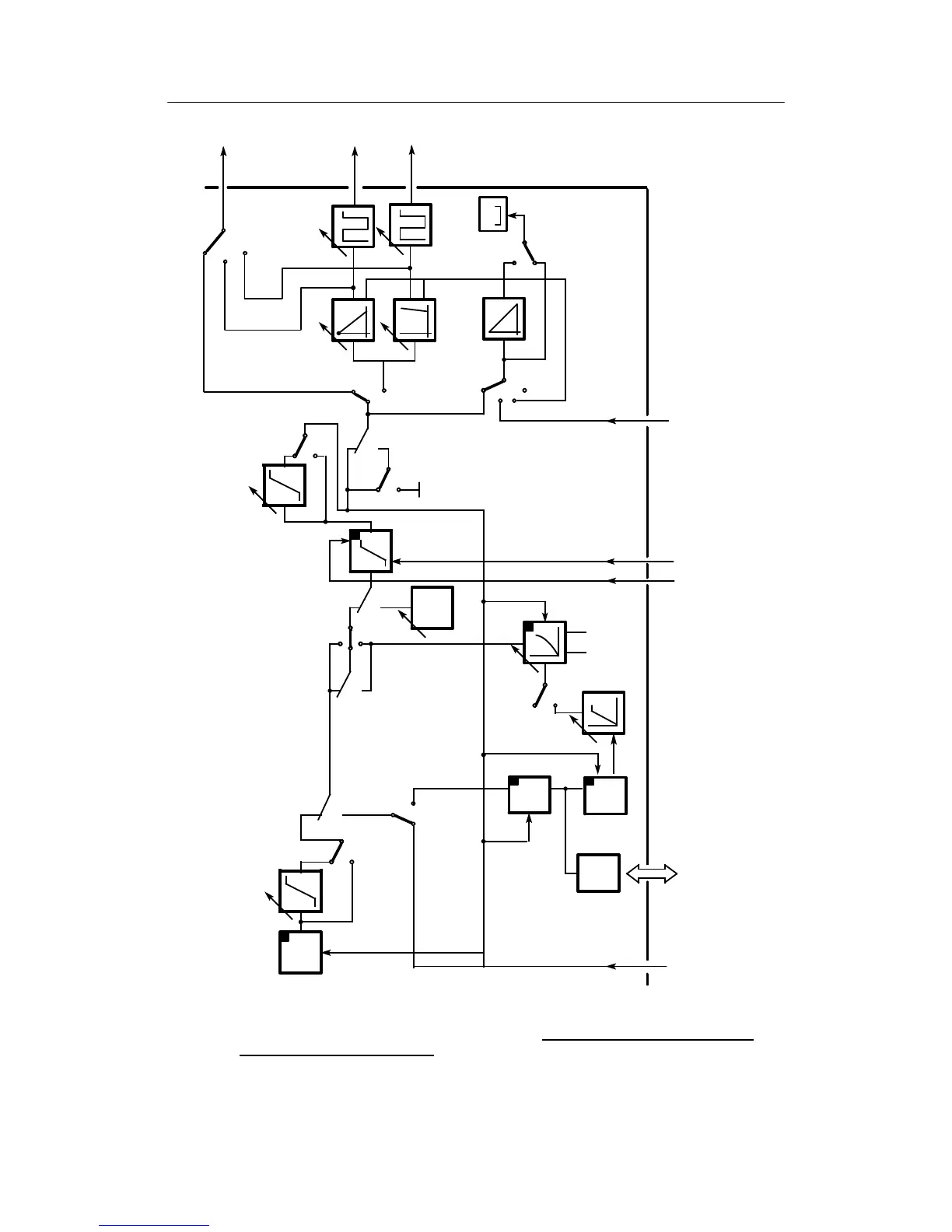
Figure 3-18 Block diagram control unit/process display (S1 = 4) manual control station with K-output
S2 = 0/two-position output S2 = 1 (manual operation has priority over tracking S49 = 1)