3 Functional description of the structure switches
3.4 Controller types (S1, S42 to S45)
Manual
86
SIPART DR21
C73000-B7476-C143-08
-Δy
y
R
0
1
+
Δy
0
2, 3
S54
1
S55
0
2
S51
1
H
0
2
S51
1
H
+
Δy
H
-Δy
H
N
Si
Si
y
S
>50
+yBL
-yBL
+y
BL
-yBL
N
+
Δy
-
Δy
S19
S57
S57
S29 S30
α
E
y
GND
y
S
≤50
rt
00
y
An
0
0
0 0 1 1 0 1 0
0
0
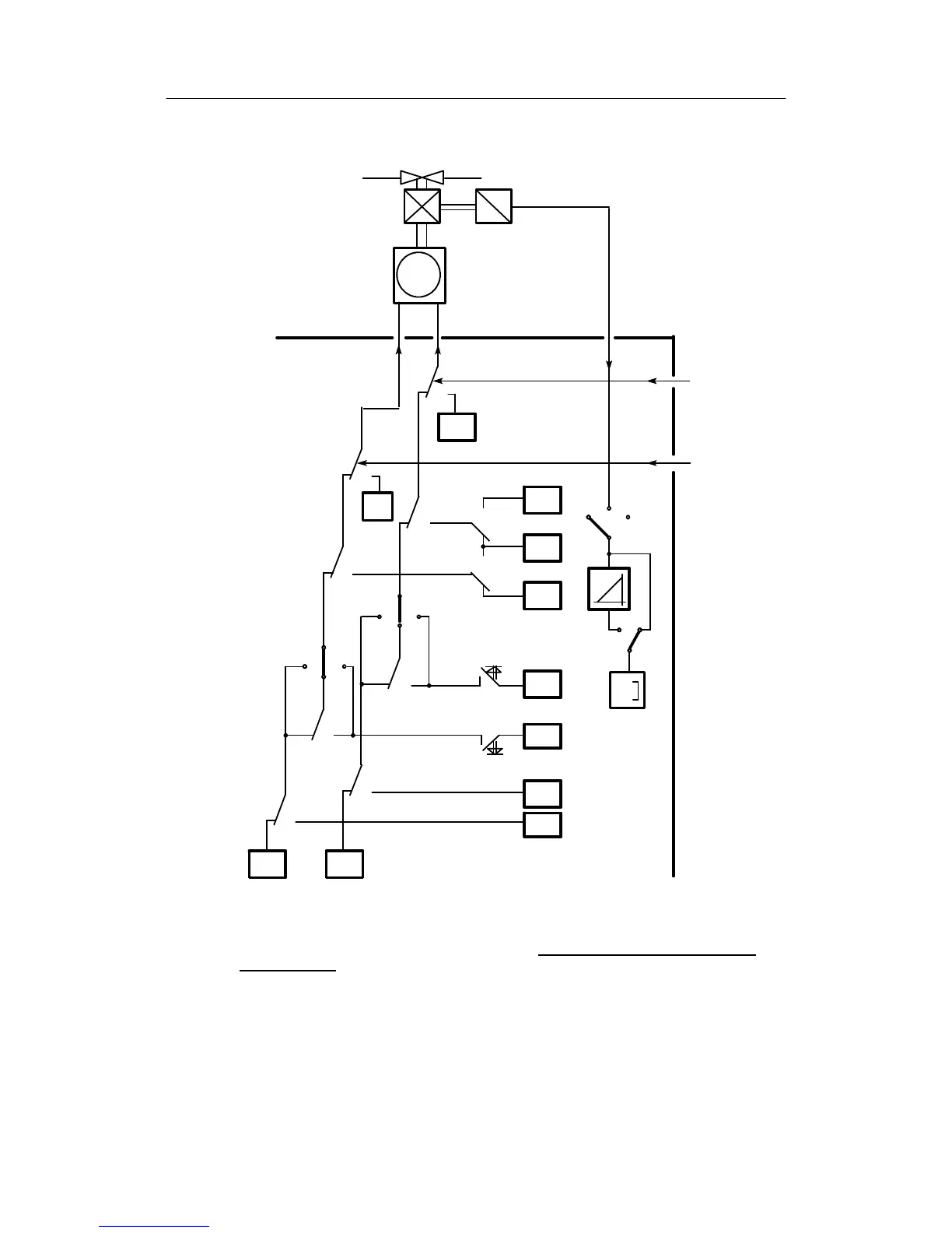
Block diagrams for S49 = 0 and manual control station S with ext. feedback (S2=3) see controller output structures
figure 3-27, page 104
Figure 3-17 Block diagram control unit/process display (S1 = 4) manual control station S with internal
feedback S2 = 2
(manual operation has priority over tracking S49 = 1)