3 Functional description of the structure switches
3.10 Other functions of the standard controller
Manual
SIPART DR21
C73000-B7476-C143-08
119
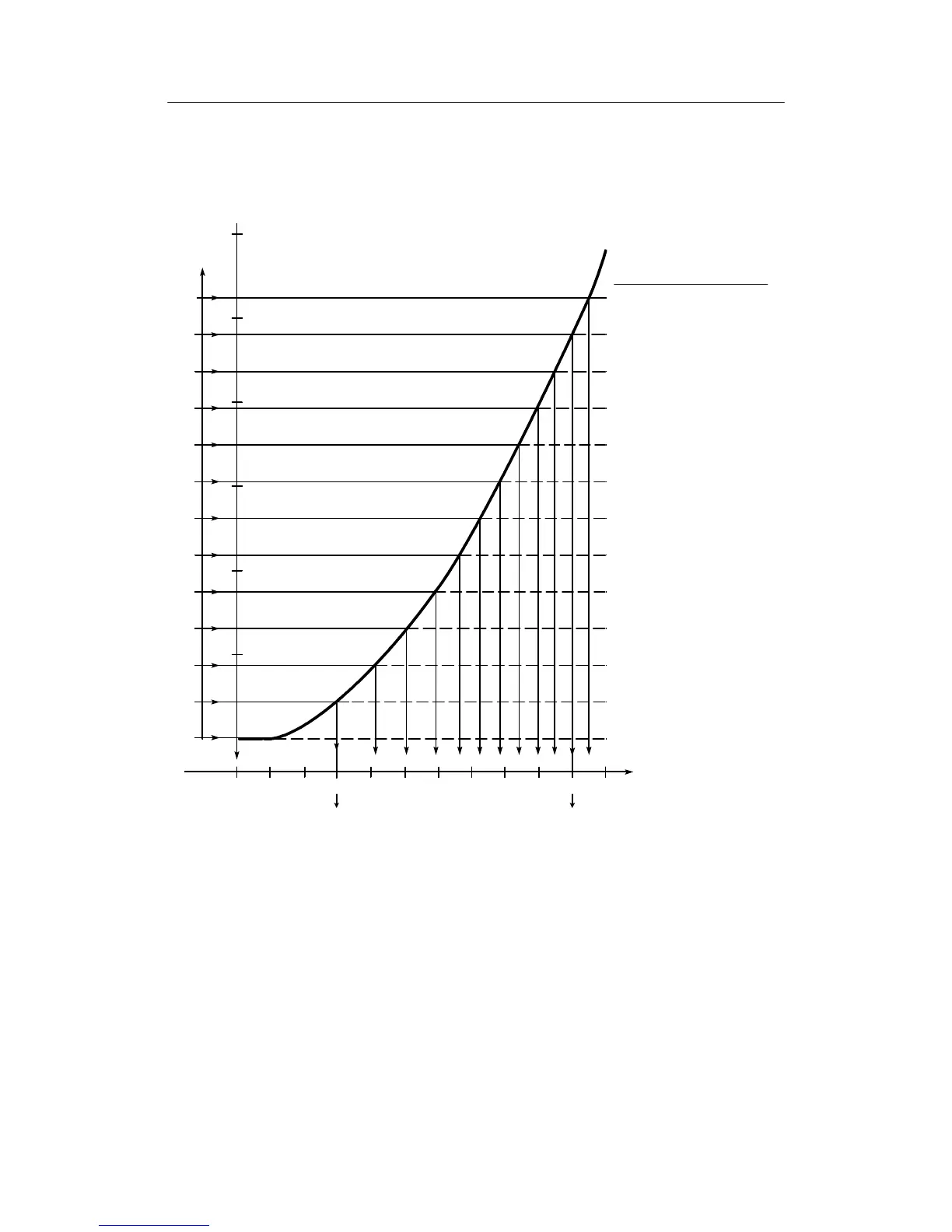
Determine the respective physical value from the appropriate function tables for every U
n
or
graphically from the corresponding curve (interpolate if necessary) and enter the value for the
respective vertex value (L
-1
to L
11
) in physical variables in the structuring mode oFPA.
U
E
8 39.526 ! L8 900
7 35.124
! L7 846
6 30.722
! L6 790
5 26.32
! L5 729
4 21.918
! L4 664
3 17.516
! L3 593
2 13.114
! L2 514
1 8.712
! L1 420
04.31
! L0 300
-1 -0.092
! L-1 0
t
A
t
E
U
E
=48.33 mV
60
50
40
30
20
10
0
0 100 200 300 400 500 600 700 800 900 1000 1200
110
100
90
80
70
60
50
40
30
20
10
0
-10
U
A
=4.31 mV
U
E
dA dE
t[˚C]
%
nUn[mV]vertex-t[˚C]
value
11 52.732
! L11 1048
10 48,33
! L10 1000
9 43.928
! L9 951
[mV]
Figure 3-35 Example of lineariz ation of a thermocouple type B Pt30Rh/Pt6, measuring range dA to dE
from 300 to 1000 C
 Loading...


