4 Installation
4.2 Electrical Connection
Manual
SIPART DR21
C73000-B7476-C143-08
139
4to20mA
AI+
L+
--
referenced to ground
~
~
49.9 Ω
6DR2800-8J
3
+
--
GND
2
1
4
I
+
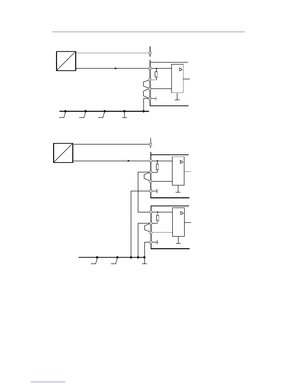
Figure 4-28 Connection of a 4 to 20 mA 2-wire transmitter supplied from controller’s L+
49.9 Ω
6DR2800-8J
3
+
--
GND
2
4
4to20mA
Controller 1
AI+
AI--
L+
~
~
Controller 2
1
49.9 Ω
6DR2800-8J
3
+
--
2
4
1
GND
+
--
I
Figure 4-29 Connection of a 4 to 20 mA 2-wire-transmitter to two instruments in s eries supplied by L+ from
one of the instruments
Every input amplifier is supplied by a differential input voltage of 0.2 to 1 V. The input amplifier
of controller 1 has an additional common mode voltage of 0.2 to 1 V which is suppressed. Sev-
eral instruments with a total common-mode voltage of up to 10 V can be connected in series.
The last controller referenced to ground may also have a ground referenced input load (e.g. AI1
or AI2 of SIPART DR21).
The permissible load voltage of the transmitter must be observed in series circuiting of load re-
sistors.