7 Application examples for configuring the controller
7.3 Configuration examples
Manual
200
SIPART DR21
C73000-B7476-C143-08
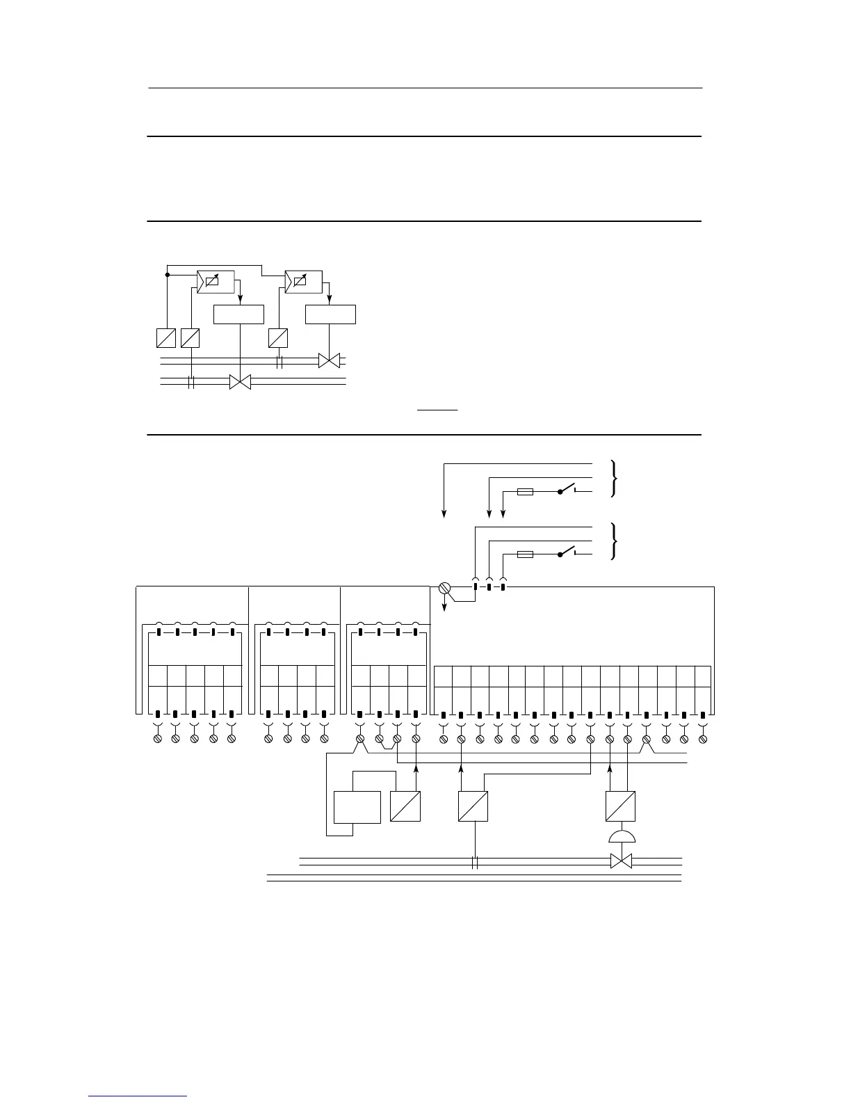
Configuration example K2 Two common mode controllers as K-controllers; external set-
point from a two-wire transmitter with external feeding;
Controlled variables from two-wire transmitters, feeding from the
SIPART DR21 controller
x1
y2
Drive
The e
ternal setpoint is looped serially through both controllers.
Since the analog inputs AI1, AI2 of the controller are referenced to
ground, the options module must be used for the current input in
one of the controllers because this can process the appropriate
common mode voltage. The setpopint w
E
is evaluated differently in
the two controllers in this example. As a result the controlled varia-
bles x1, x2 have a constant relationship with each other.
The external common setpoint can be evaluated with the online
parameters c4, c5.
w
E
=c4·w
E
+c5
If the factory setting is left in controller 1 c4 = 1, c5 = 0, the values
for c4, c5 of controller 2 in the controlled state gives the relations-
hip between the controlled variables x
1
,x
2
.
x
1
=
x2 -- c5
c4
w
E
Drive
x2
y1 y2
w
E
y1
Please read the foreword to chapter 7.1, page 193
Controller 1
Setting the structure switches controller 1:
S1 = 1
S2 = 0
S15 = 1
S17 = 3
Slot 1
AI3
Slot 2
AI4
not
used
Slot 3
Limit value
Option module
6DR2800-8J
--
I
w
E
-- R +
123 4
G
N
D
+
--
+
U-
external
w
E
I
-- +
x1
I
--+
w
E
+18V<U_<+28V
not
used
AI1
--
PE
N
L
SIP ART-DR21 standard controller
PE
N
L
UC 24 C
AC 115 V
AC 230 V
6DR2100-5 (AC230 V/115 V)
6DR2100-4 (UC 24 C)
AI1
+
AI2
--
AI2
+
DI1 DI2
DO
1
DO
2
L+ AO
123 456789101112
-Δy
L
13 14 15
+Δy
1234 12345
¡
©
¢
£
GND
GND GND