7 Application examples for configuring the controller
7.3 Configuration examples
Manual
206
SIPART DR21
C73000-B7476-C143-08
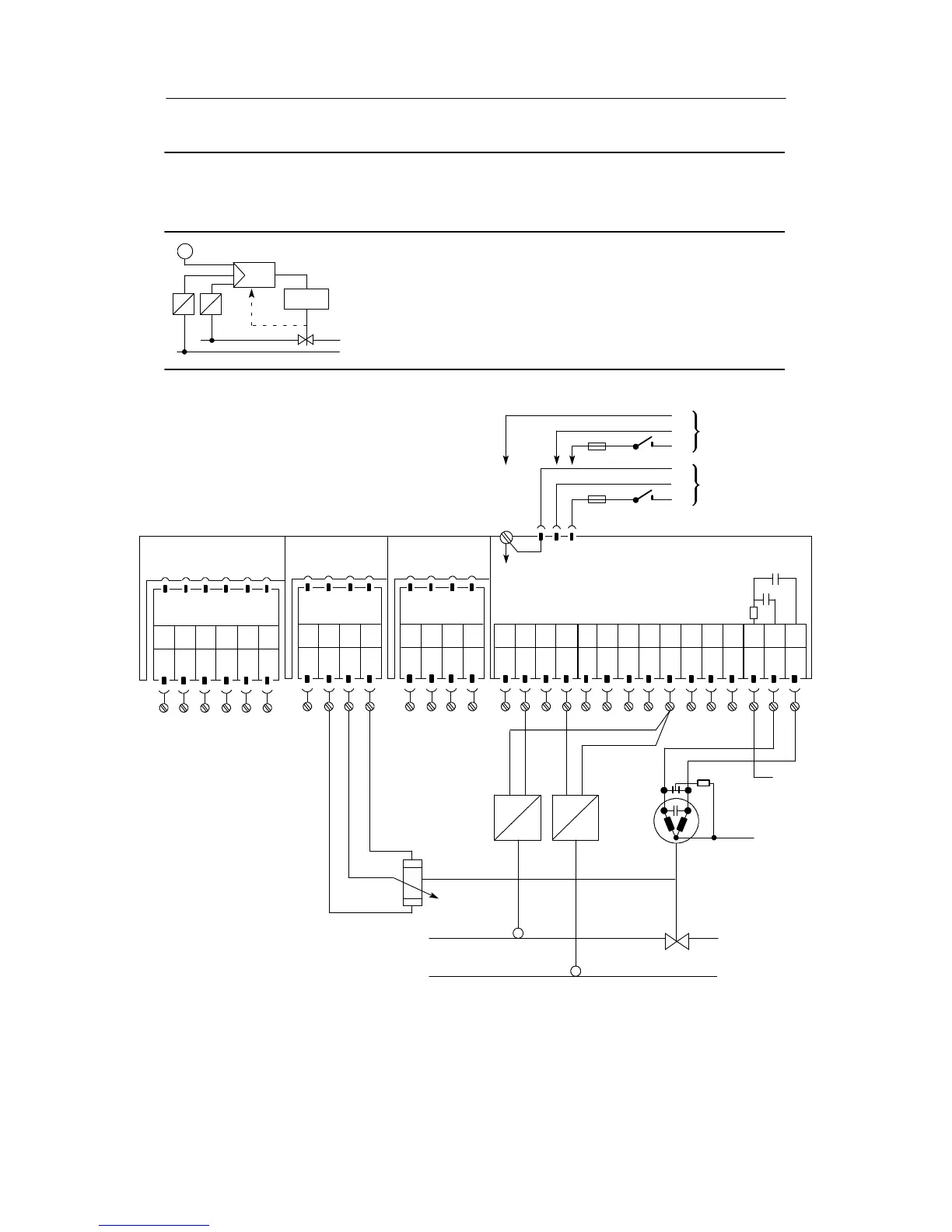
Configuration example S3 Ratio control, S-controller (internal feedback)
Commanded process variable and commanding variable directly from
two-wire transmitters
The commanded process variable x1 from the transmitter goes to the analog
input AI1, the commanding process variable is connected to the analog input AI2.
The input signal ranges are 4 to 20 mA. The feedback of the final control element
position comes from a resistance potentiometer to the analog input AI4.
The setting of the ratio factor range is described in chapter 3.4.5, page 75.
x
2
w
y
Drive
y
R
x
1
AI1
--
PE
N
L
PE
N
L
UC 24 C
AC 115 V
AC 230 V
AI1
+
AI2
--
AI2
+
DI1 DI2 DO
1
DO
2
L+ AO
123 456789101112
Setting the structure switches:
S1 = 3
S2 = 2
S4 = 2, 3
S5 = 2, 3
Slot 1
AI3
Slot 2
AI4
Spark quench-
ing internal
Slot 3
Limit value
Option module
6DR2801-8D
M1 A1 R2 M2R1 A2
123 456
not
used
M/A S E
123 4
Option module
6DR2800-8R
L+Δy
13 14 15
--Δy
S7 = 0, 1
S19 = 4
S54 = 1
Please read the foreword in chapter 7.1, pg. 193 and the warnings in chapter 2.1 (from page 17)
SIP ART DR21 standard controller
6DR2100-5 (AC230 V/115 V)
6DR2100-4 (UC 24 C)
R=R
A
+ ΔR+R
E
L
R
C
N
Perform spark
quenching according
to EMC requirements!
R
C
I
+--
R
A
R
E
S
I
+--
x
2
x
1
When using the analog inputs AI1 and AI2 the
feed voltage at the transmitter may be only 15 V
under worst case conditions.
123 4
GND
GND GND