7 Application examples for configuring the controller
7.3 Configuration examples
Manual
208
SIPART DR21
C73000-B7476-C143-08
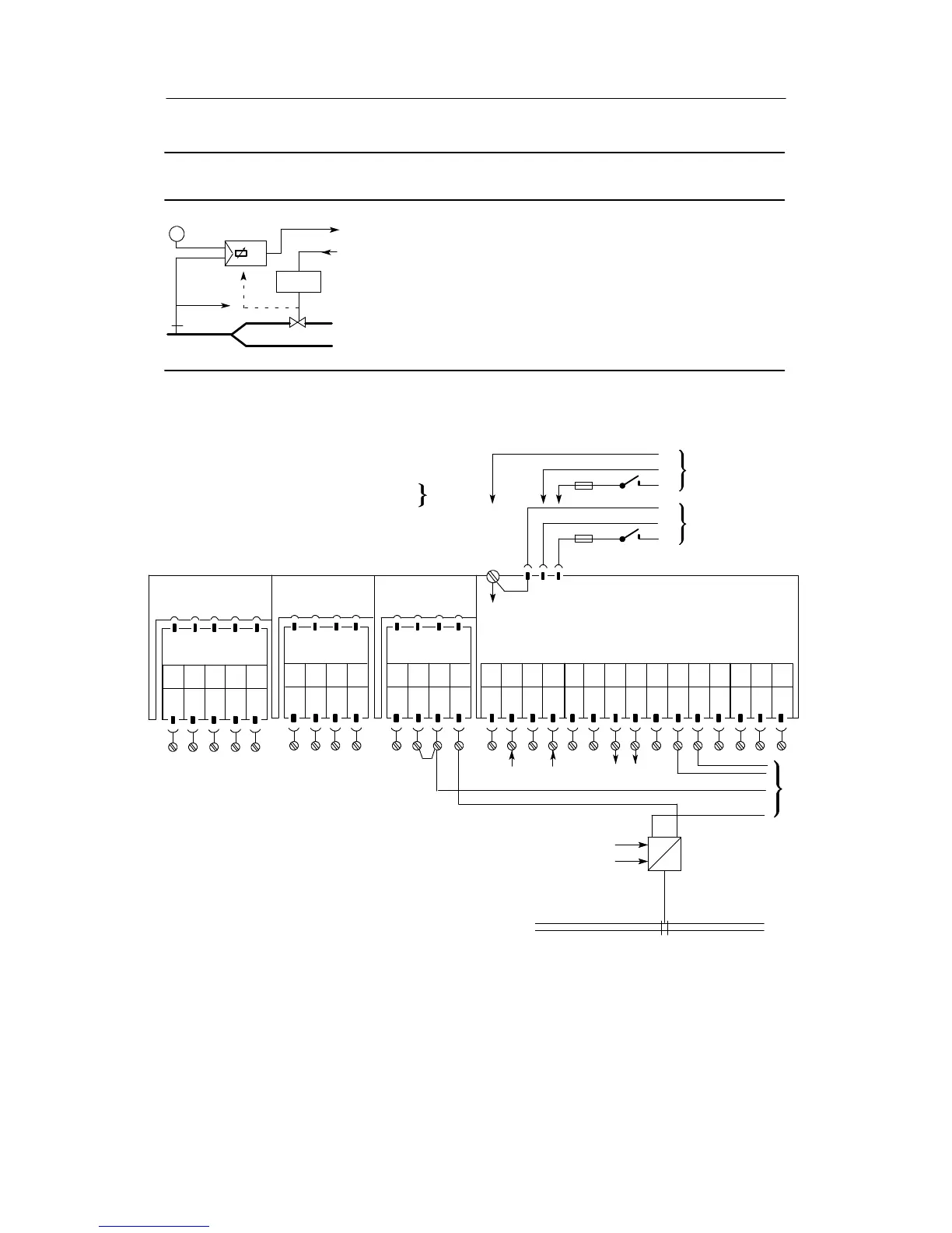
Configuration example L1 Process display
Structured as a process display, the SIPART DR21 controller can display and
monitor the process variables. If the manipulated variable y and yR is structu-
red, it can be monitored to the y display and can be adjusted with the keys (7)
and (8) with the appropriate wiring. The controlled variable x can be shown in
the red analog display (1) with structuring as x2. If the limit value A1 to A4 if
referred to x with S76, S77, S80 and shown in the green bar display (2), the
relation of the variable to be monitored to the limit values can be seen at a
glance. With the parameters dA, dE (oFP A) the variables w, x, A1 to A4 can be
displayed in their right physical variable in the w/x display (3). The y display is
made in 0 to 100%. See also fig. 3-16, page 82
w
y
Drive
wi
w
x
to the controller
to the controller
from the
controller
AI1
--
PE
N
L
PE
N
L
UC 24 C
AC 115 V
AC 230 V
AI1
+
AI2
--
AI2
+
DI1 DI2
DO
1
DO
2
L+ AO
123 456789101112
Setting the structure switches of the process display:
S1 = 4, process display
S2 = 2, S-controller internal
feedback
S15 = 0, x1 = 0
S16 = 3, x2 ! AI3
S17 = 1, we ! AI1
S19 = 2, yR ! AI2
S80 = 6, Alarms A1 to A4 in the process operation
mode can be displayed and adjusted
Slot 1
AI3
Slot 2
AI4
Slot 3
Limit value
123 45
not
used
123 4
Option module
6DR2800-8J
L+Δy
13 14 15
--Δy
Please read the foreword to chapter 7.1, page 193
SIP ART DR21 standard controller
6DR2100-5 (AC230 V/115 V)
6DR2100-4 (UC 24 C)
123 4
S42 = 2, w: int $ ext
S54 = 1, yR display
S56 = 2, w ! AO
S57 = 1, ±Δy ! DO1/2
S76 = 2, A1/A2
S77 = 2, A3/A4
referred
to x
I
--+
x2
+Δy--Δy
w
E
yR
--
+
1)
not
used
GND
R-- +
1)
for further processing e.g. in another SIPART DR controller
w
I
--+
--
+
GND GND