7 Application examples for configuring the controller
7.3 Configuration examples
Manual
210
SIPART DR21
C73000-B7476-C143-08
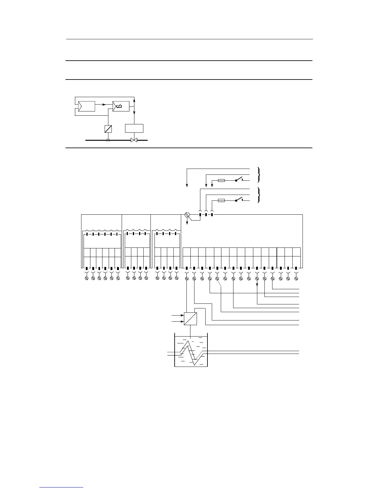
Configuration example L2 Manual control unit (HS)
Drive
y
wi
yN
yN
x2
x1
yN
Controller
Display/
manual control unit
The “Manual control unit” operating mode is implemented in the setting S1 = 4(con-
trol unit/process display). The output of a K-controller (e.g. another SIPART DR21)
canberemotecontrolledwiththeHS.
The manual control unit has priority over the controller. In the HS manual operation
has priority over tracking, in the controller tracking over manual operation. The HS
is tracked if it is not in manual operation itself, i.e. if LED (13) H external lights and
LED (12) Manual is dark. The controller is always tracked when the HS is in manual
operation, i.e. if the LED (12) on the HS is alight. If LED (12) H flashes on the con-
troller, this means that manual operation is not possible from the controller because
trackin
.
AI1
--
PE
N
L
PE
N
L
UC 24 C
AC 115 V
AC 230 V
AI1
+
AI2
--
AI2
+
DI1 DI2 L+ AO
123 456789101112
Slot 1
AI3
Slot 2
AI4
Slot 3
Limit value
1234 5 6
not
used
1234
Option module
6DR2800-8J
L+Δy
13 14 15
--Δy
SIP ART DR21 standard controller
6DR2100-5 (AC230 V/115 V)
6DR2100-4 (UC 24 C)
12 3 4
not
used
R-- +
x2
I
--
+
--
+
yN ly
¡
©
¢
£
¥
¦
§
Manual control unit
Setting the structure switches of the manual control unit:
S1 = 4, control unit S18 = 2, yN $ AI2
S2 = 0, K-controller S23 = 0, CB = 0
S15 = 0, x1 = 0 S49 = 1
S16 = 1, x2 ! AI1 S60 = 1, H ! DO1
Please read the foreword to chapter 7.1, page 193
¤
¨
GND
GND GND
DO
1
DO
2