3 Functional description of the structure switches
3.4 Controller types (S1, S42 to S45)
Manual
SIPART DR21
C73000-B7476-C143-08
79
The ratio factor v (at xd = 0) is determined partly by the transmission factors K of the
transmitters (measuring ranges).
x
1
=Q
G
⋅ K
G
with the values from the example
100 %
3000 m
3
/h
K
G
=
x
2
=Q
L
⋅ K
L
100 %
12,000 m
3
/h
K
L
=
v= =
Q
G
Q
L
x
1
x
2
⋅
with
Q
G
Q
L
1
L
⋅ λ
=
v=
1
L
⋅ λ
K
G
K
L
K
G
K
L
⋅
With the values from the example
v=
1
λ
⋅
1
4
100 % ⋅ h ⋅ 12,000 m
3
3,000 m
3
⋅ 100 % ⋅ h
⋅
the result is
v=
1
λ
i.e. the choice of the transmitter ranges has been made so
that
G
K
L
=
1
L
corresponds to
The desired adjustment range of λ gives:
vA = =
1
λ
E
1
1
25
=0,8
vE = =
1
λ
A
1
0,75
= 1,333
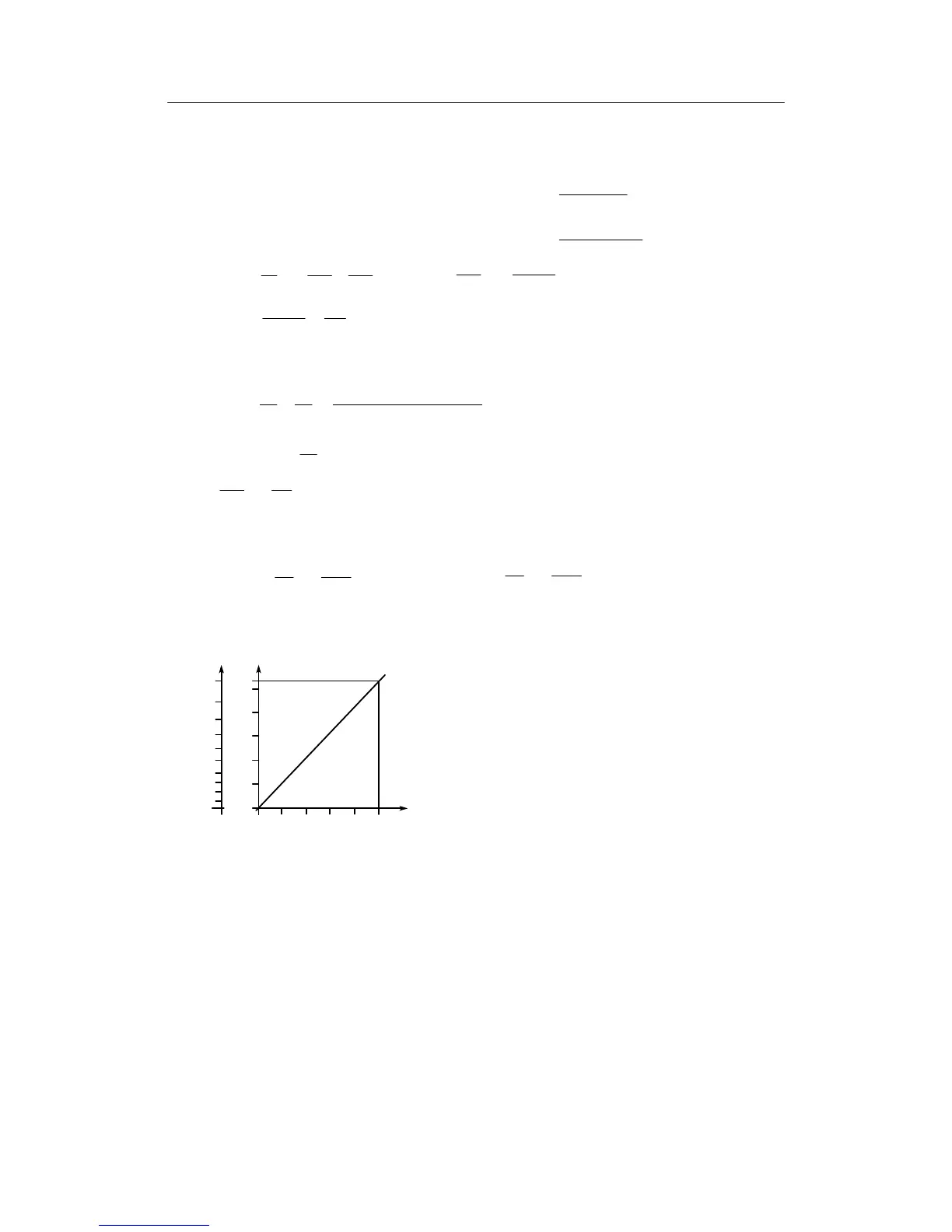
vA and vE are set in the structuring mode oFPA. By setting the nominal ratio wv from 0 to 1
the ratio factor v can now be adjusted from 0.8 to 1.33 or the air factor λ from 1.25 to 0.75.
0.75
1.2
1.25
0.8
0.9
1
1.1
1.2
0.2 0.6
1.33
1.3
1
0.80.40
0.8
1.1
0.9
1
wv
v
λ
Figure 3-14 Relationship ratio factor v and air factor λ to standardized nominal ratio wv
If the combustion is also to take place at small flow volumes with excess air, the constant c
must be set negative. Figure 3-14 shows the gas-/air ratio in the controlled state at different
air factors λ andc=0aswellasatλ = 1 and c <0, i.e. with excess air.