3 Functional description of the structure switches
3.4 Controller types (S1, S42 to S45)
Manual
84
SIPART DR21
C73000-B7476-C143-08
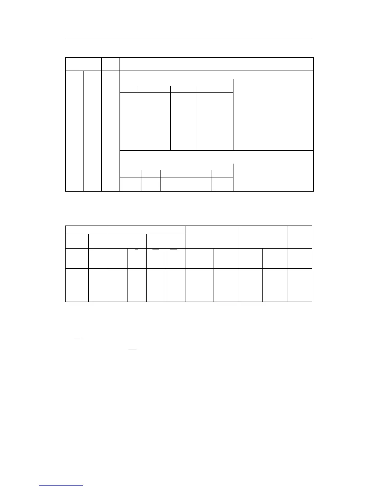
Structure
switches
Posi-
tion
Function
S81 Switching the w/x-digital display
Display order
I II III IV
[0] x/xv w/wv -- --
1 x/xv w/wv x1/xv --
2 x/xv w/wi1/wv -- wE/wvE/wi2
3 x/xv w/wi1/wv x1/xv wE/wvE/wi2
4 x/xv -- -- --
5 -- w/wv -- --
6 -- -- x1/xv --
7 xv wv x1 w
Identification of the displayed variables by the w- or x-signal lamp:
1 = steady light, 0.5 = flashing light, 0 = off
Display order
I II III IV
1 0 0.5 (0 at S81=6) 0 x-signal lamp
0 1 0 0,5 w-signal lamp
Table 3-11 Display levels (S81)
Control s igna ls Message signals
or
Int∨CB
CB
1)
Inter-
nal
Inter-
nal
LED
C
LED
RB RC
5)
S44=0 S44=1 wi ±Δw/BA
0 0 0 1 0 1
3)
we(n)
2) 3)
we(n)
2)
no yes 0
7)
1 0 0 0 0 1
3)
we(n)
2) 3)
we(n)
2)
no no 1
0 1 1 1 1 0
3)
wi(n,↗)
3)
wi(n,↗) yes no 1
1
6)
1
6)
1
6)
0
6)
1
6)
1
6) 3)
we(n)
2)6)
SH
4)6)
no
6)
no
6)
1
6)
1)
The table is shown for static CB-switching without acknowledgement (S41 = 0).
2)
Source for w
E
at S85 = 0, 1, (4, 5 as of software version -A5), is w
EA
, which is assigned by S17 or at S85 = 2, 3 w
ES
,
which is fed in via the SES.
3)
Tracking only takes place at S45=0 and only w
ES
and wi to the active setpoint. When feeding in via w
EA
the feeding
instrument must be tracked.
4)
Only to be used as a flag pointer when no analog feedback is possible from the fed instrument.
5)
RC = no K-setpoint generator operation, wi not adjustable.
6)
Factory setting
7)
wired-or-connection of Int = RB and CB supplies Int∨CB
No S-setpoint optentiometer operation, Δw-keys not active
(n) tracked to the value active before switching, therefore bumpless switching
↗ adjustable
Table 3-12 Setpoint switching setpoint generator S/K, S1 = 4 process display/control unit