direction of the device (forward = line direction). Changing this parameter also results in a polarity reversal of
the ground current inputs Ι
N
or Ι
NS
.
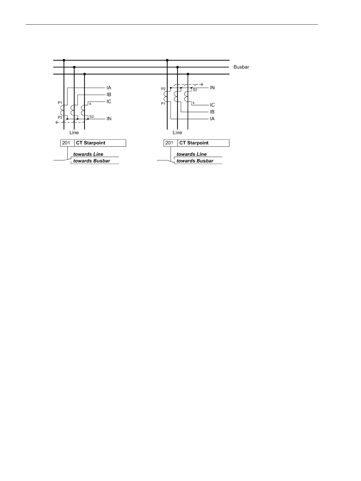
[polung-stromwandler-020313-kn, 1, en_US]
Figure 2-3 Polarity of current transformers
Current Connection Ι4 (Power System)
Here, it is communicated to the device whether the ground current of the current transformer neutral point is
connected to the fourth current input (Ι
4
). This corresponds to the Holmgreen connection, (see connection
example in C Connection Examples). In this case, parameter 280 Holmgr. for Σi is set to YES. In all other
cases, even if the ground current of the own line is measured via a separate ground current transformer, enter
the setting NO. This setting exclusively affects the function “Current Sum Monitoring” (see Section 2.8.1 Meas-
urement Supervision).
Current Connection (Power System)
Via parameter 251 CT Connect. a special connection of the current transformers can be determined.
The standard connection is A, B, C, (Gnd). It may only be changed if the device is set to measure one or
more ground currents via two current inputs. The standard connection applies to all other cases.
The following diagram illustrates a special connection.
Functions
2.1 General
36 SIPROTEC 4, 7SJ61, Manual
C53000-G1140-C210-6, Edition 05.2016

 Loading...


