[7sj62-64-mess-2erdstroeme-20070301, 1, en_US]
Figure 2-4
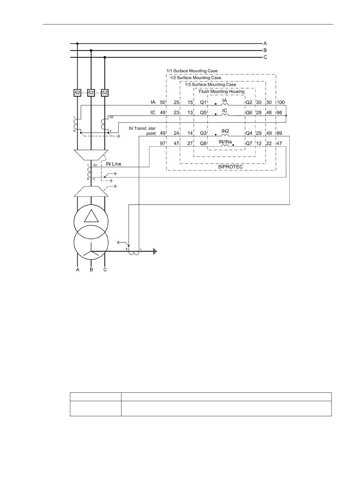
Measurement of two ground currents, example
The phase currents Ι
A
and Ι
C
must be connected to the first current input (terminals Q1, Q2) and to the third
(terminals Q5, Q6). At the fourth input (terminals Q7, Q8) the ground current Ι
N
or Ι
NS
is connected as usual,
in this case the ground current of the line. A second ground current, in this case the transformer neutral point
current, is connected to the second current input Ι
N2
(terminals Q3, Q4).
The settings A,G2,C,G; G->B or A,G2,C,G; G2->B must be used here. Both define the connection of a
ground current Ι
N2
at the second current input (terminals Q3, Q4). The settings only differ in the calculation of
Ι
B
. In case of A,G2,C,G; G->B, the phase current Ι
B
is determined by phase currents Ι
A
and Ι
C
as well as the
measured ground current Ι
N
or Ι
NS
at the fourth current input. In case of A,G2,C,G; G2->B, the phase
current Ι
B
is determined by phase currents Ι
A
and Ι
C
as well as the measured ground current Ι
N2
at the second
current input. The setting must be set according to system requirements.
The assignment of the protection functions to the ground current inputs in special connections is set out in
the following table.
Current Input
Function
Ι
N2
Time overcurrent protection ground (Section 2.2 Overcurrent Protection 50, 51, 50N,
51N)
Functions
2.1 General
SIPROTEC 4, 7SJ61, Manual 37
C53000-G1140-C210-6, Edition 05.2016

 Loading...


