2.16 Overvoltage Protection (ANSI 59)
107
7UM61 Manual
C53000-G1176-C127-3
Settings Address 4107 VALUES serves to specify the measured quantities used by the protec-
tion feature. The default setting (normal case) is specified for phase-to-phase voltages
(= U-ph-ph). The phase-earth voltages should be selected for low-voltage machines
with grounded neutral conductor (= U-ph-e). It should be noted that even if phase-
earth voltages are selected as measured quantities, the setting values of the protec-
tion functions are referred to phase-to-phase voltages.
The setting of limit values and time delays of the overvoltage protection depends on
the speed with which the voltage regulator can regulate voltage variations. The pro-
tection must not intervene in the regulation process of the fault-free functioning voltage
regulator. For this reason, the two-stage characteristic must always be above the
voltage time characteristic of the regulation procedure.
The long-time stage 4102 U> and 4103 T U> must intervene in case of steady-state
overvoltages. It is set to approximately 110 % to 115 % U
N
and, depending on the reg-
ulator speed, to a range between 1.5 s and 5 s.
In case of a full-load rejection of the generator, the voltage increases first in relation to
the transient voltage. Only then the voltage regulator reduces it again to its nominal
value. The U>> stage is set generally as a short-time stage in a way that the transient
procedure for a full-load rejection does not lead to a tripping. For example, for 4104
U>> about 130% U
N
with a delay 4105 T U>> of zero to 0.5 s are typical values.
All setting times are additional time delays which do not include the operating times
(measuring time, dropout time) of the protective function.
The dropout ratio at the address 4106 DOUT RATIO can be adapted in small steps to
the operating conditions and used for highly precise signalizations (e.g. network infeed
of wind power stations).
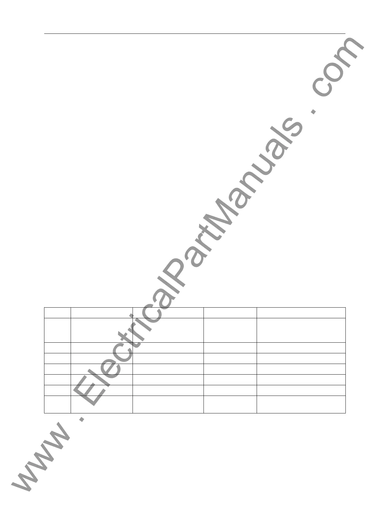
2.16.3 Settings
Addresses which have an appended "A" can only be changed with DIGSI, under Ad-
ditional Settings.
Addr. Parameter Setting Options Default Setting Comments
4101 OVERVOLTAGE OFF
ON
Block relay
OFF Overvoltage Protection
4102 U> 30.0 .. 170.0 V 115.0 V U> Pickup
4103 T U> 0.00 .. 60.00 sec; ∞ 3.00 sec T U> Time Delay
4104 U>> 30.0 .. 170.0 V 130.0 V U>> Pickup
4105 T U>> 0.00 .. 60.00 sec; ∞ 0.50 sec T U>> Time Delay
4106A DOUT RATIO 0.90 .. 0.99 0.95 U>, U>> Drop Out Ratio
4107A VALUES U-ph-ph
U-ph-e
U-ph-ph Measurement Values
www . ElectricalPartManuals . com

 Loading...


