2 Functions
56
7UM61 Manual
C53000-G1176-C127-3
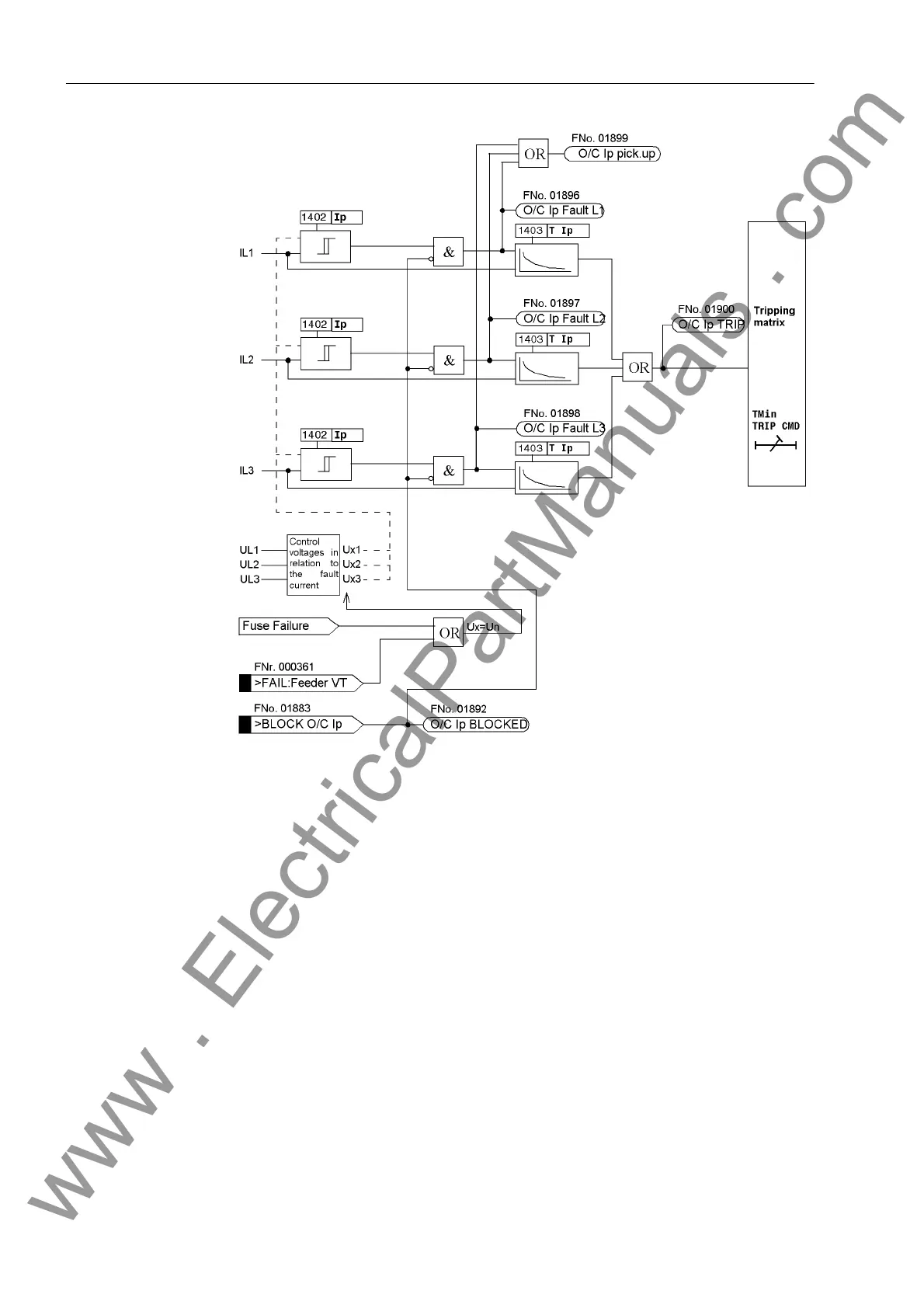
Figure 2-13 Logic Diagram of the Voltage Restraint Inverse Time Overcurrent Protection
The reduction of the current pickup threshold on decreasing voltage (control voltage
allocation) is performed phase in accordance with Table 2-3.
2.8.2 Setting Notes
General Inverse overcurrent time protection is only effective and available if address 114 O/C
PROT. Ip was set to with IEC or with ANSI. If the function is not needed it is set
to Disabled.
Ip Overcurrent
Stage
The address 1401 O/C Ip serves to switch the function ON or OFF or to block only
the trip command (Block relay). It must be noted that, for the inverse overcurrent
time protection, a safety factor of about 1.1 has been included between the pick-up
value and the setting value. This means that a pickup will only occur if a current of
about 1.1 times of the setting value is present. The dropout occurs as soon as the
value falls below 95% of the pickup value.
www . ElectricalPartManuals . com

 Loading...


