2 Functions
218
7UM61 Manual
C53000-G1176-C127-3
2.35.4.4 Information List
2.35.5 Date and Time Stamping
The integrated date/time management allows exact time-specific allocation of events,
for example in the operational and fault indications or the minimum/maximum value
lists.
2.35.5.1 Functional Description
Mode of Operation The time can be influenced by
• internal RTC (Real Time Clock),
• external synchronisation sources (DCF77, IRIG B, SyncBox, IEC 60 870–5–103),
• external minute pulses via binary input.
Note
On device delivery the internal clock RTC is always set by default as synchronisation
source, regardless of whether the device is equipped with a system interface or not. If
the time synchronisation is to use an external source, it must be selected.
The procedure for changing the synchronization source is explained in detail in the
SIPROTEC
®
4 System Description.
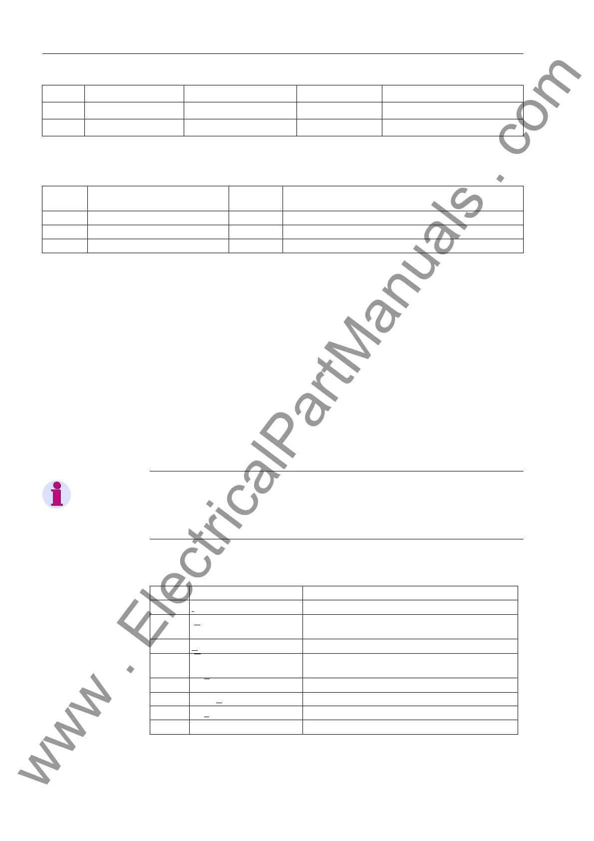
405 POST REC. TIME 0.05 .. 0.50 sec 0.10 sec Captured Waveform after Event
406 BinIn CAPT.TIME 0.10 .. 5.00 sec; ∞ 0.50 sec Capture Time via Binary Input
No. Information Type of In-
formation
Comments
- FltRecSta IE Fault Recording Start
4 >Trig.Wave.Cap. EM >Trigger Waveform Capture
203 Wave. deleted AM_W Waveform data deleted
Addr. Parameter Setting Options Default Setting Comments
No. Operating Mode Comments
1Internal Internal synchronization using RTC (default)
2IEC 60870-5-103 External synchronization using system interface (IEC
60 870–5–103)
3P
ROFIBUS DP External synchronization using PROFIBUS interface
4IRIG B Time signal External synchronization using IRIG B (telegram
format IRIG-B000)
5 DCF
77 Time signal External synchronization using DCF 77
6 Sync. Box Time signal External synchronization using SIMEAS Sync. Box
7Puls
e via binary input External synchronization with pulse via binary input
8 Field bus External synchronization using Modbus interface
www . ElectricalPartManuals . com

 Loading...


