2.35 Ancillary Functions
215
7UM61 Manual
C53000-G1176-C127-3
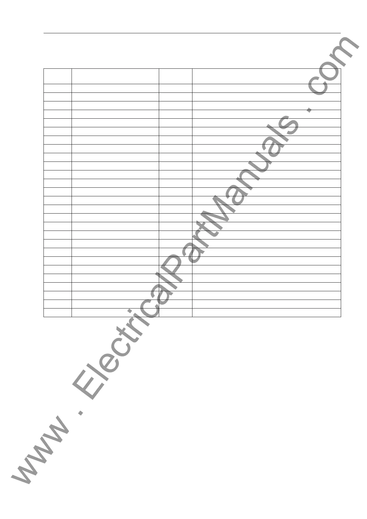
2.35.2.2 Information List
2.35.3 Set Points (Measured Values)
2.35.3.1 Functional Description
Limit Value Moni-
torings
SIPROTEC
®
7UM61 allows limit levels for important measured and counter values to
be set. If during operation a value transgresses one of these limits, the device gener-
ates an alarm which is displayed as an operational indication. As for all operational in-
dications, it is possible to output the information to LED and/or output relay and via in-
terfaces. In contrast to the actual protective functions, such as time-overcurrent
protection or overload protection, this monitoring program runs in the background and
may not respond promptly during a fault if the measured values change rapidly and
protective functions pick up. Moreover, since an indication is not generated until the
set limit value has been transgressed several times, these monitoring functions cannot
respond immediately before a protection trip.
With the 7UM61, only the limit value of the undercurrent protection IL< is configured
when the device is delivered from the factory. Further limit values can be configured if
No. Information Type of In-
formation
Comments
601 IL1 = MW I L1
602 IL2 = MW I L2
603 IL3 = MW I L3
605 I1 = MW I1 (positive sequence)
606 I2 = MW I2 (negative sequence)
621 UL1E= MW U L1-E
622 UL2E= MW U L2-E
623 UL3E= MW U L3-E
624 UL12= MW U L12
625 UL23= MW U L23
626 UL31= MW U L31
627 UE = MW Displacement voltage UE
629 U1 = MW U1 (positive sequence)
630 U2 = MW U2 (negative sequence)
641 P = MW P (active power)
642 Q = MW Q (reactive power)
644 Freq= MW Frequency
645 S = MW S (apparent power)
650 UE3h= MW UE 3rd harmonic
765 U/f = MW (U/Un) / (f/fn)
830 IEE = MW Senstive Earth Fault Current
831 3I0 = MW 3I0 (zero sequence)
832 U0 = MW U0 (zero sequence)
901 PF = MW Power Factor
902 PHI = MW Power angle
903 R = MW Resistance
904 X = MW Reactance
www . ElectricalPartManuals . com

 Loading...


