4.4 Thermal Overload Protection (ANSI 49)
315
7UM61 Manual
C53000-G1176-C127-3
4.4 Thermal Overload Protection (ANSI 49)
Setting Ranges / Increments
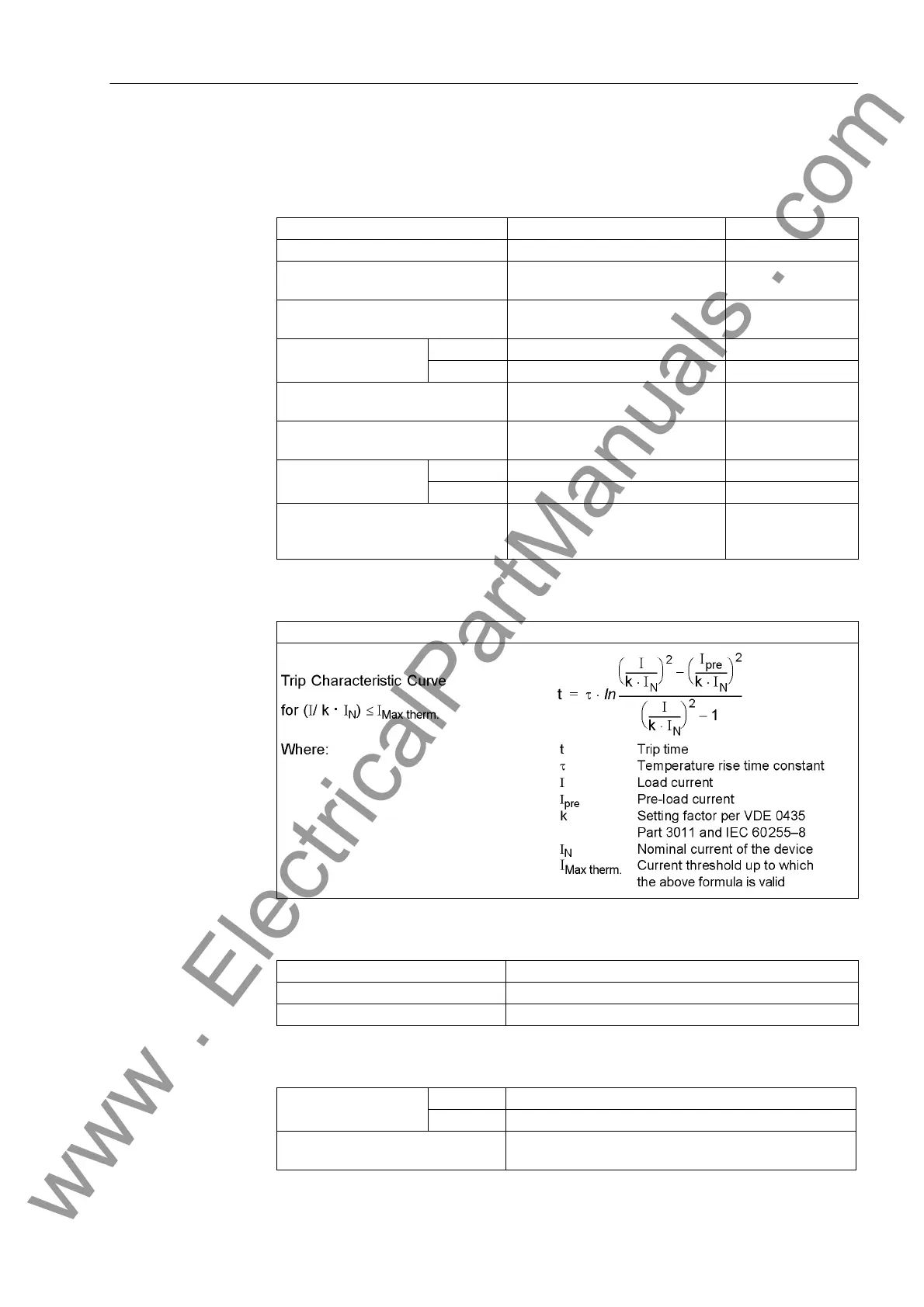
Tripping Characteristics
Dropout ratios
Tolerances
K-Factor per IEC 60,255-8 0.10 to 4.00 Increments 0.01
Time Constant τ 30 s to 32000 s Increments 1 s
Extension of Time Constant at
Standstill
1.0 to 10.0 Increments 0.1
Warning overtemperatureΘ
Alarm
/Θ
Trip
referred to the tripping temperature
70 % to 100 % Increments 1 %
Current Overload I
Alarm
for I
N
= 1 A 0.10 A to 4.00 A Increments 0.01 A
for I
N
= 1 A 0.50 A to 20.00 A Increments 0.05 A
Nominal Overtemperature (for I
Nom
)40° to 200 °C / 104 °F to 392 °F (Increments 1 °C)
(Increments 1.8 °F)
Coolant Temperature for Scaling 40° to 300 °C / 104 °F to 572 °F (Increments 1 °C)
(Increments 1.8 °F)
Limit current I
Limit
for I
N
= 1 A 0.50 A to 8.00 A Increments 0.01 A
for I
N
= 5 A 2.00 A to 40.00 A Increments 0.05 A
Dropout Time after Emergency Start-
ing
T
Emergency Start
10 s to 15000 s Increments 1 s
see also Figure 2-15
Θ/Θ
Off
Dropout with Θ
Alarm
Θ/Θ
Alarm
approx. 0.99
I/IAlarm approx. 0.95
referred to k · I
N
for I
N
= 1 A 2 % or 10 mA ; class 2 % acc. to IEC 60255-8
for I
N
= 5 A 2 % or 50 mA ; class 2 % acc. to IEC 60255-8
referred to Trip Time 3 %, or 1 s, Class 3 % acc. to IEC 60255-8
for I/(k ·I
N
) > 1,25
www . ElectricalPartManuals . com

 Loading...


