4 Technical Data
308
7UM61 Manual
C53000-G1176-C127-3
4.3 Inverse-Time Overcurrent Protection (ANSI 51V)
Setting Ranges / Increments
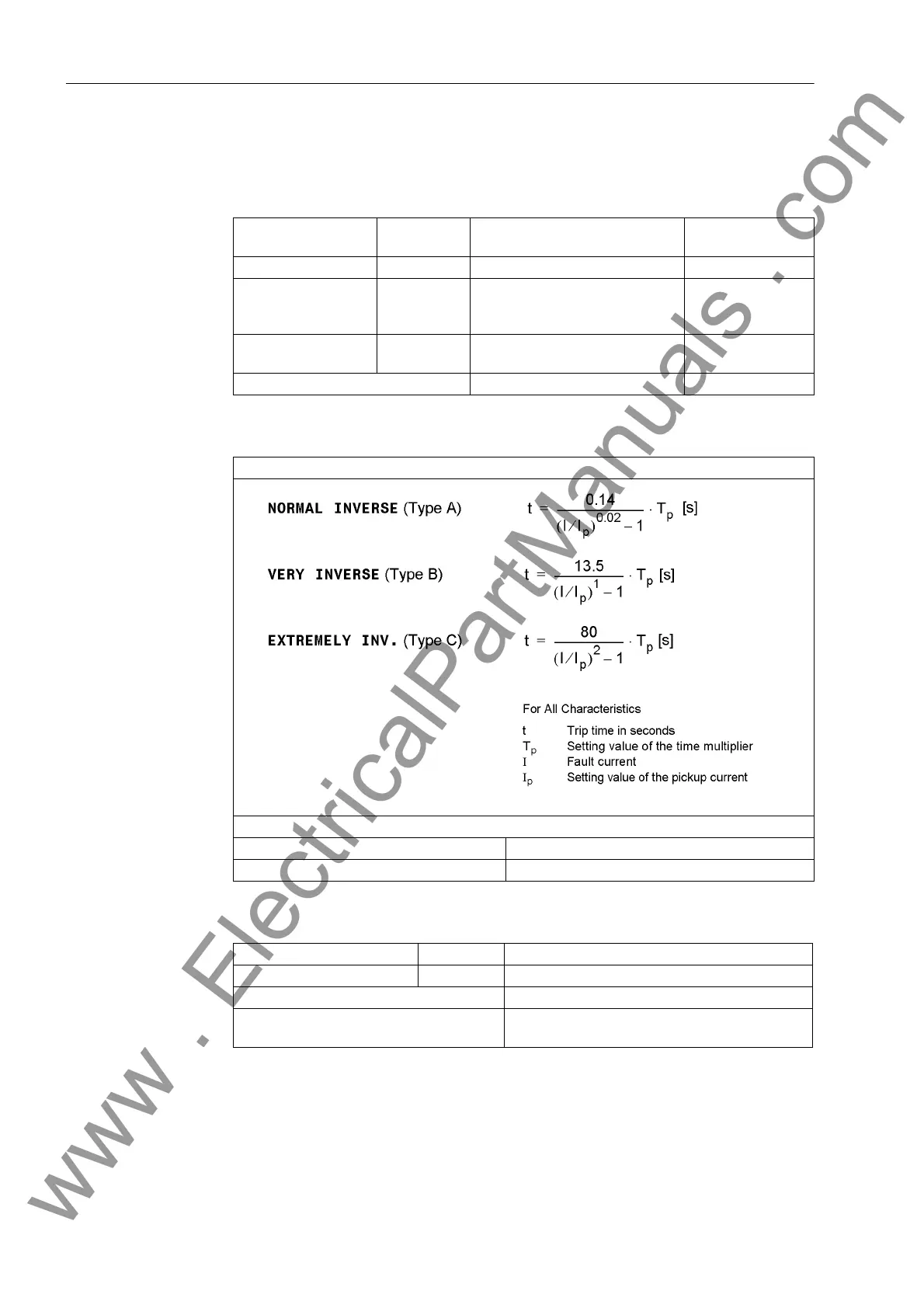
Trip Time Curves acc. to IEC
Tolerances
Pickup current I
p
(Phase)
for I
N
= 1 A 0.10 A to 4.00 A Increments 0.01 A
for I
N
= 5A 0.50 A to 20.00 A Increments 0.05 A
Time Multipliers T for
I
p
IEC curves
0.05 s to 3.20 s
or ∞ (ineffective)
Increments 0.01 s
Time Multiplier D for I
p
ANSI curves
0.50 to 15.00
or ∞ (ineffective)
Increments 0.01
Undervoltage enableU< 10.0 V to 125.0 V Increments 0.1V
As per IEC 60255-3, Section 3.5.2 or BS 142 (see also Figure 4-1)
The trip times for I/I
p
≥ 20 are identical to those for I/I
p
= 20.
Pickup Threshold approx. 1.10 · I
p
Dropout Threshold Approx. 1.05 · I
p
for I
p
/I
N
≥ 0.3
Pickup Currents I
p
for I
N
= 1 A 1 % of setting value or 10 mA
for I
N
= 5A 5 % of setting value or 50 mA
Pickup Threshold U< 1 % of setting value, or 0.5 V
Time for 2 ≤ I/I
p
≤ 20 5 % of reference (calculated) value +1 % current
tolerance, or 40 ms
www . ElectricalPartManuals . com

 Loading...


