2.30 Threshold supervision
183
7UM61 Manual
C53000-G1176-C127-3
2.30 Threshold supervision
This function monitors the thresholds of selected measured values (for overshoot or
undershoot). The processing speed of this function is so high that it can be used for
protection applications. The necessary logical combinations can be implemented by
means of CFC.
The principal use is for high-speed supervision and automatic functions as well as ap-
plication-specific protection functions (e.g. power plant decoupling) which are not in-
cluded in the scope of protection functions.
2.30.1 Functional Description
Mode of Operation There are 6 threshold supervision blocks, 3 each for overshoot and undershoot of the
threshold. As result a logical indication is output that can be further processed by the
CFC.
A total of 9 processable measured values are available, all of which can be evaluated
as percentages. Each threshold block can be allocated one of these 9 measured
values. As for all other protection functions, the measured values are referred to as
secondary quantities.
The following table shows the useable measured values. The threshold values are
queried once per cycle.
The following figure shows an overview of the logic.
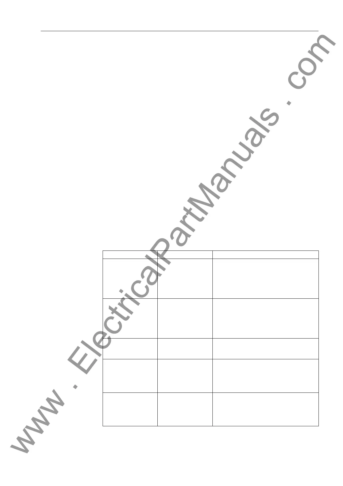
Table 2-10 Measured Values
Measured Value Scaling Explanation
P
(Active power)
P/S
N,sec
· 100 % The positive sequence system quantities for
U and I are formed once per cycle from the
sampled values. From the result, P is calculat-
ed. The measuring result is subject to the
angle correction (address 204 CT ANGLE
W0) in the current path.
Q
(Reactive power)
Q/S
N,sec
· 100 % The positive sequence system quantities for
U and I are formed once per cycle from the
sampled values. From the result, Q is calcu-
lated. The measuring result is subject to the
angle correction (address 204 CT ANGLE
W0) in the current path.
∆P
(Active power change)
∆P/S
N,sec
· 100 % The active power difference is calculated from
the active power over a measuring window of
3 cycles.
U1
(Positive sequence
voltage)
U1/U
N,sec
· 100 % The positive sequence voltage is determined
from the phase-to-earth voltages on the basis
of the definition equation for symmetrical
components. The calculation is performed
once per cycle.
U2
(Negative sequence
voltage)
U2/U
N,sec
· 100 % The negative sequence voltage is determined
from the phase-to-earth voltages on the basis
of the definition equation for symmetrical
components. The calculation is performed
once per cycle.
www . ElectricalPartManuals . com

 Loading...


