A Appendix
352
7UM61 Manual
C53000-G1176-C127-3
A.1 Ordering Information and Accessories
A.1.1 Ordering Information
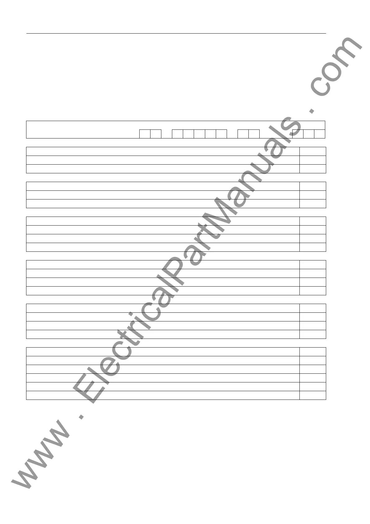
A.1.1.1 7UM61
6 7 8 9 10 11 12 13 14 17 18 19
Machine Protection 7UM61 — — A0+
Number of Binary Inputs and Outputs Pos. 6
Housing 1/3 19'', 7 BI, 11 BO, 1 Live Status Contact 1
Housing 1/2 19'', 15 BI, 19 BO, 1 Live Status Contact 2
Nominal current Pos. 7
I
N
= 1 A 1
I
N
= 5 A 5
Auxiliary Voltage (Power Supply, Binary Input Threshold) Pos. 8
DC 24 to 48 V, binary input threshold 19 V 2
DC 60 to 125 V, binary input threshold 19 V 4
DC 110 to 250 V, AC 115/230 V, Binary Input Threshold DC 88 V 5
Construction Pos. 9
Surface-mounting case for panel, 2-tier terminals top/bottom B
Flush mounting case, plug-in terminals (2/3-pole connector) D
Flush mounting case, screw-type terminals (direct connection / ring and spade lugs) E
Region-specific Default / Language Settings and Function Versions Pos. 10
Region DE, 50 Hz, IEC, Language German (Language can be changed) A
Region World, 50/60 Hz, IEC/ANSI, Language English (Language can be changed) B
Region US, 60 Hz, ANSI, Language American English (Language can be changed) C
System Interface (Rear Side, Port B) Pos. 11
No system interface 0
IEC Protocol, electrical RS 232 1
IEC-Protocol, electrical RS 485 2
IEC Protocol, Optical, 820 nm, ST Connector 3
for more interface options see Additional Information L 9
www . ElectricalPartManuals . com

 Loading...


