2.3 Power System Data 1
37
7UM61 Manual
C53000-G1176-C127-3
ATEX100 Parameter 274 ATEX100 allows compliance with PTB requirements (special require-
ments in Germany) for thermal replicas. If this parameter is set to YES, all thermal rep-
licas of the 7UM61 are stored on auxiliary power supply failure. As soon as the supply
voltage returns, the thermal replicas continue operating with the stored values. If the
parameter is set to NO, the calculated overtemperature values of all thermal replicas
are reset to zero on auxiliary power supply failure.
Command Duration Address 280 is used to set the minimum time TMin TRIP CMD the tripping contacts
will remain closed. This setting applies to all protective functions that initiate tripping.
Current Flow Moni-
toring
Address 281 BkrClosed I MIN corresponds to the threshold value of the integrated
current flow monitoring feature. This setting is used for the elapsed-time meter and the
overload protection. If the set threshold current is exceeded, the circuit breaker is con-
sidered closed and the power system is considered to be in operation. In the case of
overload protection, this criterion distinguishes between standstill and motion of the
machine to be protected.
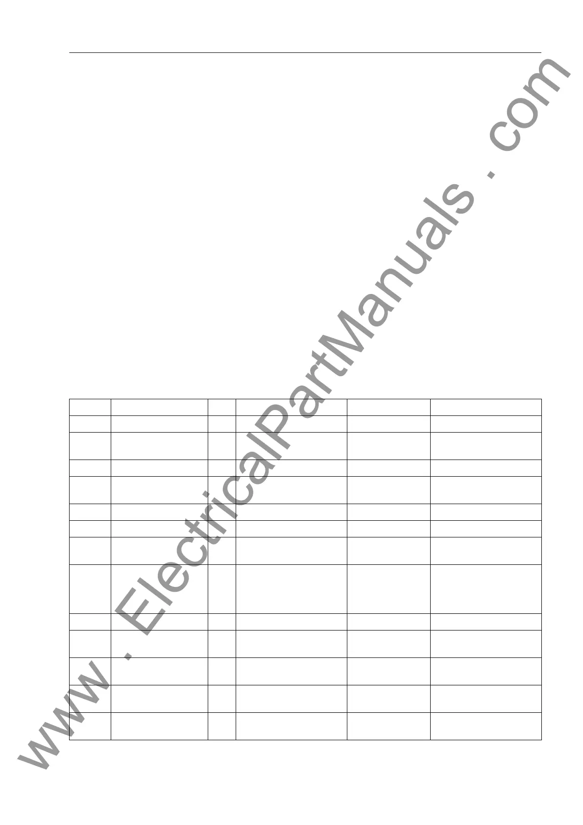
2.3.2 Settings
Addresses which have an appended "A" can only be changed with DIGSI, under Ad-
ditional Settings.
The table indicates region-specific presettings. Column C (configuration) indicates the
corresponding secondary nominal current of the current transformer.
Addr. Parameter C Setting Options Default Setting Comments
204 CT ANGLE W0 -5.00 .. 5.00 ° 0.00 ° Correction Angle CT W0
210 CT Starpoint towards machine
towards starpt.
towards machine CT Starpoint
211 CT PRIMARY 10 .. 50000 A 500 A CT Rated Primary Current
212 CT SECONDARY 1A
5A
1A CT Rated Secondary
Current
213 FACTOR IEE 1.0 .. 300.0 60.0 CT Ratio Prim./Sec. Iee
221 Unom PRIMARY 0.10 .. 400.00 kV 6.30 kV Rated Primary Voltage
222 Unom SECONDARY 100 .. 125 V 100 V Rated Secondary Voltage
(Ph-Ph)
223 UE CONNECTION neutr. transf.
broken delta
Not connected
any VT
neutr. transf. UE Connection
224 FACTOR UE 1.0 .. 2500.0 36.4 VT Ratio Prim./Sec. Ue
225A Uph / Udelta 1.00 .. 3.00 1.73 Matching Ratio Ph.-VT to
Broken-Delta-VT
270 Rated Frequency 50 Hz
60 Hz
50 Hz Rated Frequency
271 PHASE SEQ. L1 L2 L3
L1 L3 L2
L1 L2 L3 Phase Sequence
272 SCHEME Busbar
Unit transf.
Busbar Scheme Configuration
www . ElectricalPartManuals . com

 Loading...


