2 Functions
142
7UM61 Manual
C53000-G1176-C127-3
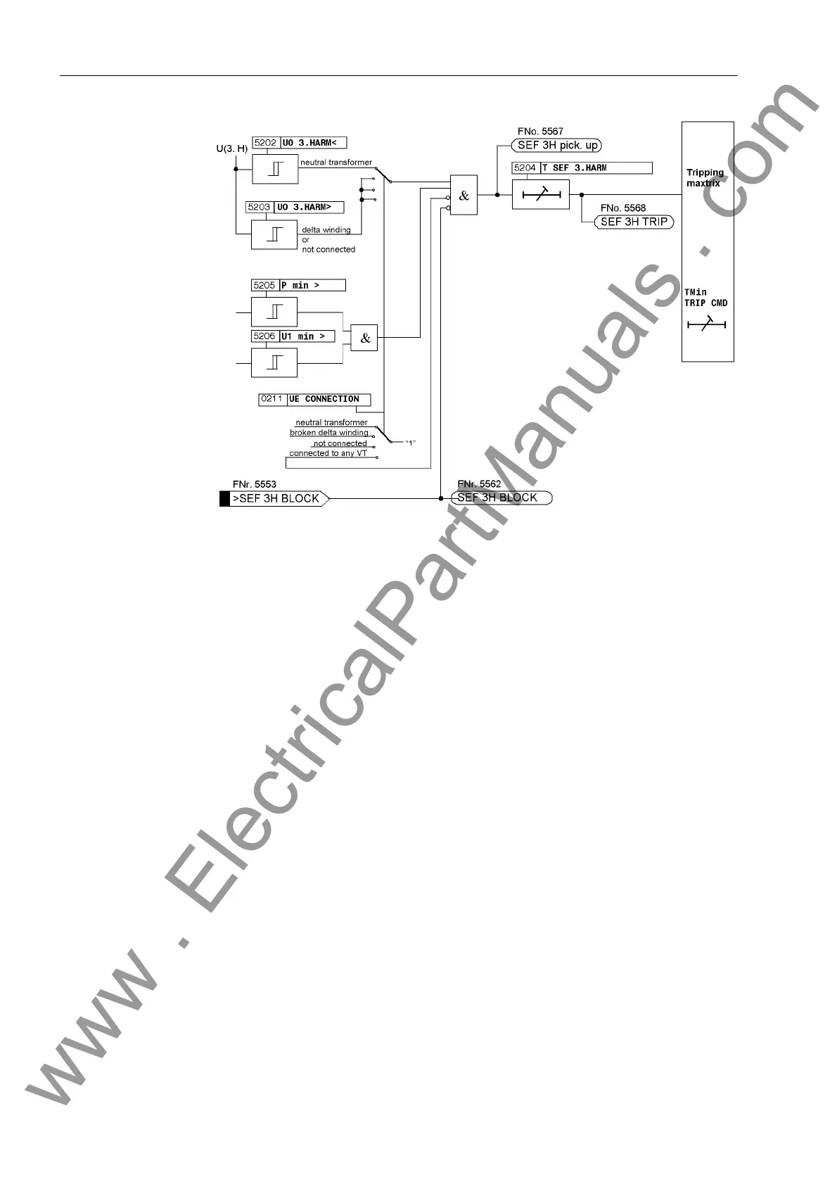
Figure 2-50 Logic Diagram of 100% Stator Earth Fault Protection
2.23.2 Setting Notes
General The 100% Stator earth fault protection is only fully effective and available if address
152 SEF 3rd HARM. is set to Enabled during configuration. If the function is not
required Disabled is set. Address 5201 SEF 3rd HARM. serves to switch the func-
tion ON or OFF or to block only the trip command (Block relay).
Connection Type Depending on the system conditions, at address 223 UE CONNECTION the user spec-
ified during the project configuration if the displacement voltage U
0
is tapped via a
neutral transformer (neutr. transf.) or via the broken delta winding of an earthing
transformer (broken delta) and fed to the protection device. If it is not possible to
make the displacement voltage available to the protection device as a measured
quantity, computed quantities are used and Not connected must be set. The option
any VT is selected if the voltage input of the 7UM61 is to be used for measuring any
other voltage instead of for earth fault protection. In this case the 100% stator earth
fault protection function is ineffective.
Pickup Value for
3rd Harmonic
Depending on the selection of the connection type, only one of the two setting param-
eters 5202 or 5203 is accessible.
The setting values can only be determined within the framework of a primary test. The
following applies in general:
•The 5202 U0 3.HARM< undervoltage stage is relevant for a connection to a trans-
former in the starpoint. The pickup value should be chosen as low as possible.
•The 5203 U0 3.HARM> overvoltage stage is relevant for a connection via the
broken delta winding of an earthing transformer and for a not connected, but inter-
nally calculated displacement voltage.
www . ElectricalPartManuals . com

 Loading...


