2 Functions
216
7UM61 Manual
C53000-G1176-C127-3
their measured and metered values have been set accordingly in CFC (see SIPRO-
TEC 4 System Description /1/).
2.35.3.2 Setting Notes
Limit Values Limit settings are entered under MEASUREMENTS in the sub-menu LIMITS
SETTING by overwriting the default values.
2.35.3.3 Information List
2.35.4 Oscillographic Fault Records
The Multi-Functional Protective Relay 7UM61 is equipped with a fault memory which
scans either the instantaneous values or the rms values of various measured quanti-
ties for storage in a ring buffer.
2.35.4.1 Functional Description
Mode of Operation The instantaneous values of measured values
i
L1
, i
L2
, i
L3
, i
EE
and u
L1
, u
L2
, u
L3
, u
E
are scanned at intervals of 1.25 ms (for 50 Hz) or 1.04 ms (for 60 Hz), and stored in a
ring buffer (16 samples per cycle). For a fault, the data are stored for an adjustable
period of time, but not more than 5 seconds.
The rms values of the measured quantities
I
1
, I
2
, I
EE
; U
1
, U
E
, P, Q, ϕ, f–f
N
, R and X
can be deposited in a ring buffer, one measured value per period. R and X are the pos-
itive sequence impedances. For a fault, the data are stored for an adjustable period of
time, but not more than 80 seconds.
Up to 8 fault records can be recorded in this buffer. The fault record memory is auto-
matically updated with every new fault, so no acknowledgment is required. The fault
record buffer can also be started with protection pickup, via binary input, operator in-
terface or serial interface.
The data can be retrieved via the serial interfaces by means of a PC and evaluated
with the protection data processing program DIGSI
®
4 and the graphic analysis soft-
ware SIGRA
®
4. The latter graphically represents the data recorded during the system
fault and calculates additional information such as impedance or rms values from the
measured values. Currents and voltages can be presented as desired as primary or
secondary values. Binary signal traces (marks) of particular events e.g. "pickup", "trip-
ping" are also recorded.
If the device has a serial system interface (IEC 60870–5–103), fault recording data can
be passed on to a central device (e.g. SICAM) via this interface. Data are evaluated
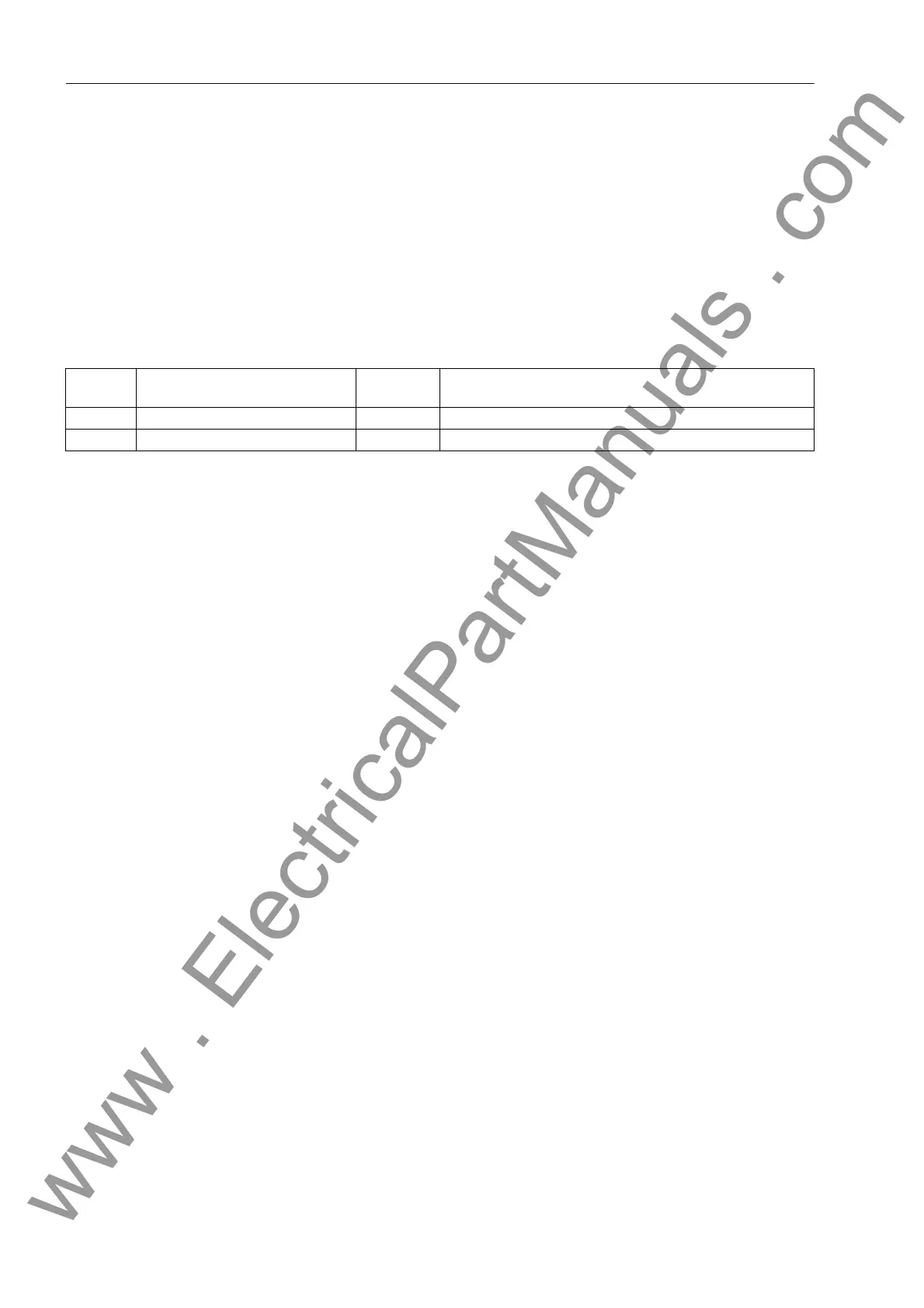
No. Information Type of In-
formation
Comments
- IL< GW IL< under current
284 SP. I< AM Set Point I< alarm
www . ElectricalPartManuals . com

 Loading...


