3 Mounting and Commissioning
252
7UM61 Manual
C53000-G1176-C127-3
3.1.3 Mounting
3.1.3.1 Panel Flush Mounting
Depending on the version, the housing size can be
1
/
3
or
1
/2.
• Remove the 4 covers on the corners of the front plate. This gives access to the 4 or
6 slots in the mounting flange.
• Insert the device into the control panel section and tighten it with 4 screws. For di-
mensions refer to Section 4.26.
• Replace the 4 covers.
• Connect a solid low-ohmic protection and system earthing to the rear of the unit with
at least one M4 screw. The cross section of the wire used must correspond to the
maximum cross section area connection, but be at least 2.5 mm
2
.
• Connections use the plug terminals or screw terminals on the rear side of the device
in accordance the circuit diagram. For screw connections with forked lugs or direct
connection, before inserting wires the screws must be tightened so that the screw
heads are flush with the outer edge of the connection block. A ring lug must be
centred in the connection chamber, in such a way that the screw thread fits in the
hole of the lug. The SIPROTEC 4 System Description/1/ specifications regarding
wire cross sections, tightening torques, bending radii and strain relief must always
be observed.
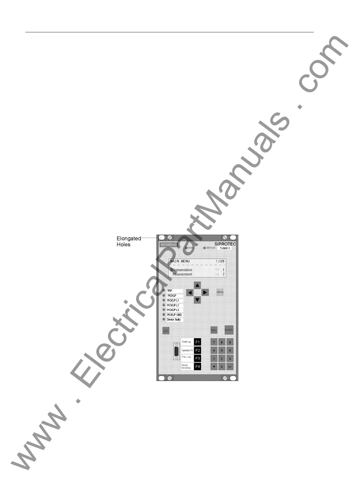
Figure 3-10 Panel flush mounting of a 7UM611
www . ElectricalPartManuals . com

 Loading...


