2 Functions
34
7UM61 Manual
C53000-G1176-C127-3
2.3 Power System Data 1
The device requires certain network and power system data so that it can be adapted
to its intended functions in accordance with application. These include, for instance,
rated power system and transformer data, measured quantity polarities and connec-
tion, breaker properties etc. There are also certain parameters common to all func-
tions, i.e. not associated with a specific protection, control or monitoring function.
Section P.System Data 1 describes these.
2.3.1 Setting Notes
General The Power System Data 1 can be changed via the operator or service interface from
a PC using DIGSI
®
.
In DIGSI
®
double-click Settings to display the data available.
Connection of the
Current Transform-
er Set
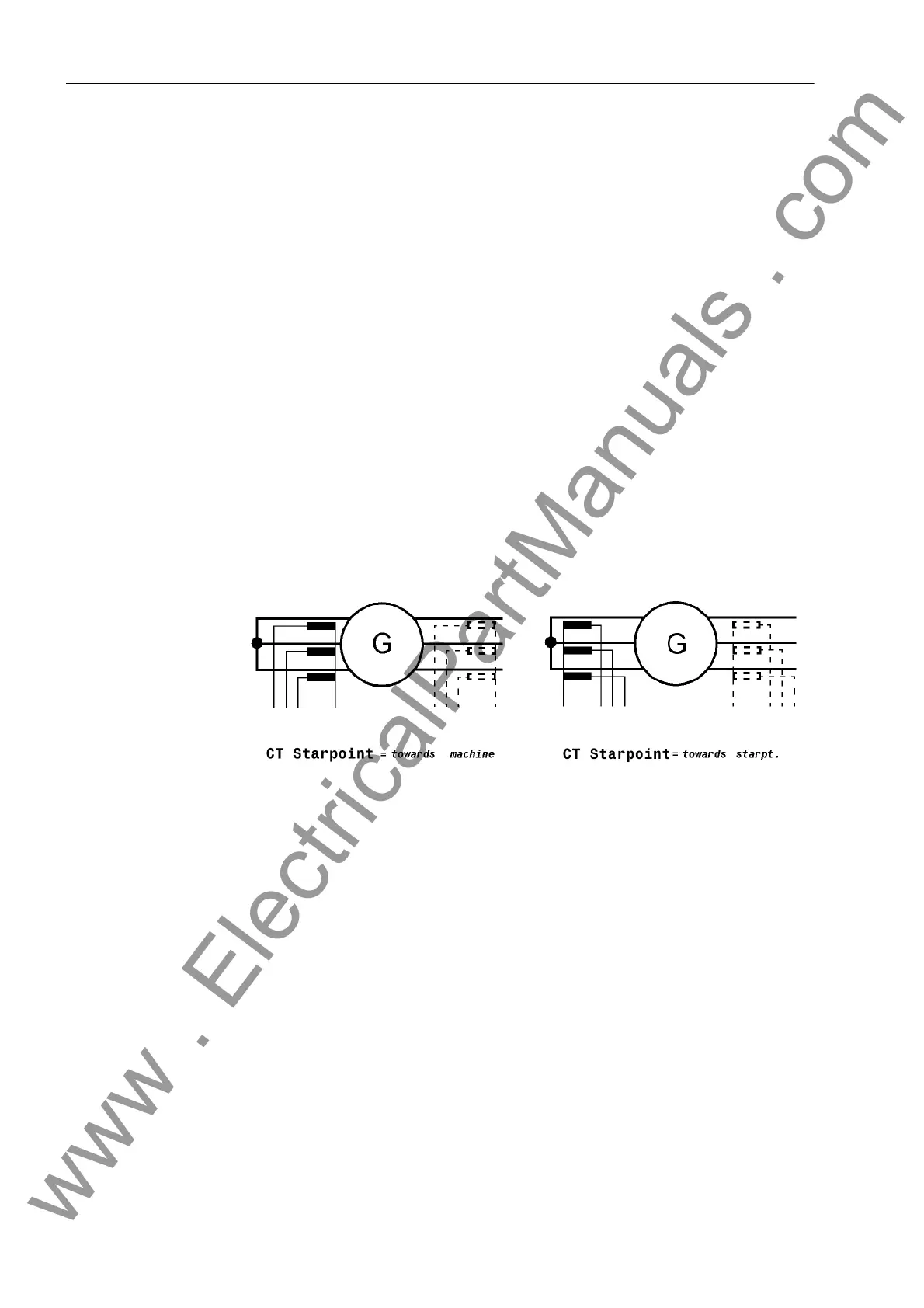
In address 210 CT Starpoint the polarity of the current transformers must be en-
tered, i.e. the location of the CT starpoint. This setting determines the measuring di-
rection of the device (forwards = line direction). The following figure shows the defini-
tion even in cases where there are no starpoint CTs.
Figure 2-2 Location of the CT Starpoints
Nominal Values of
the Transformers
At addresses 211 CT PRIMARY and 212 CT SECONDARY, information is entered re-
garding the primary and secondary current rating of the current transformers. It is im-
portant to ensure that the rated secondary current of the current transformer matches
the rated current of the device, otherwise the device will incorrectly calculate primary
data.
W0 Correction
Angle
A correction of the angle faults of the current and voltage transformers is particularly
important with regard to reverse power protection, as in this case a very low active
power is computed from a very high apparent power (for small cos ϕ).
At address 204 CT ANGLE W0 a constant correction angle can be entered for the CT.
The angle fault difference ∆ϕ between the current and voltage transformers is partic-
ularly important in this context. As a correction, the sum of the mean angle errors of
the current transformers and voltage transformers is set. The corrective value can be
determined during machine commissioning (see Section Mounting and Commission-
ing).
www . ElectricalPartManuals . com

 Loading...


