A.4 Default Settings
373
7UM61 Manual
C53000-G1176-C127-3
A.4 Default Settings
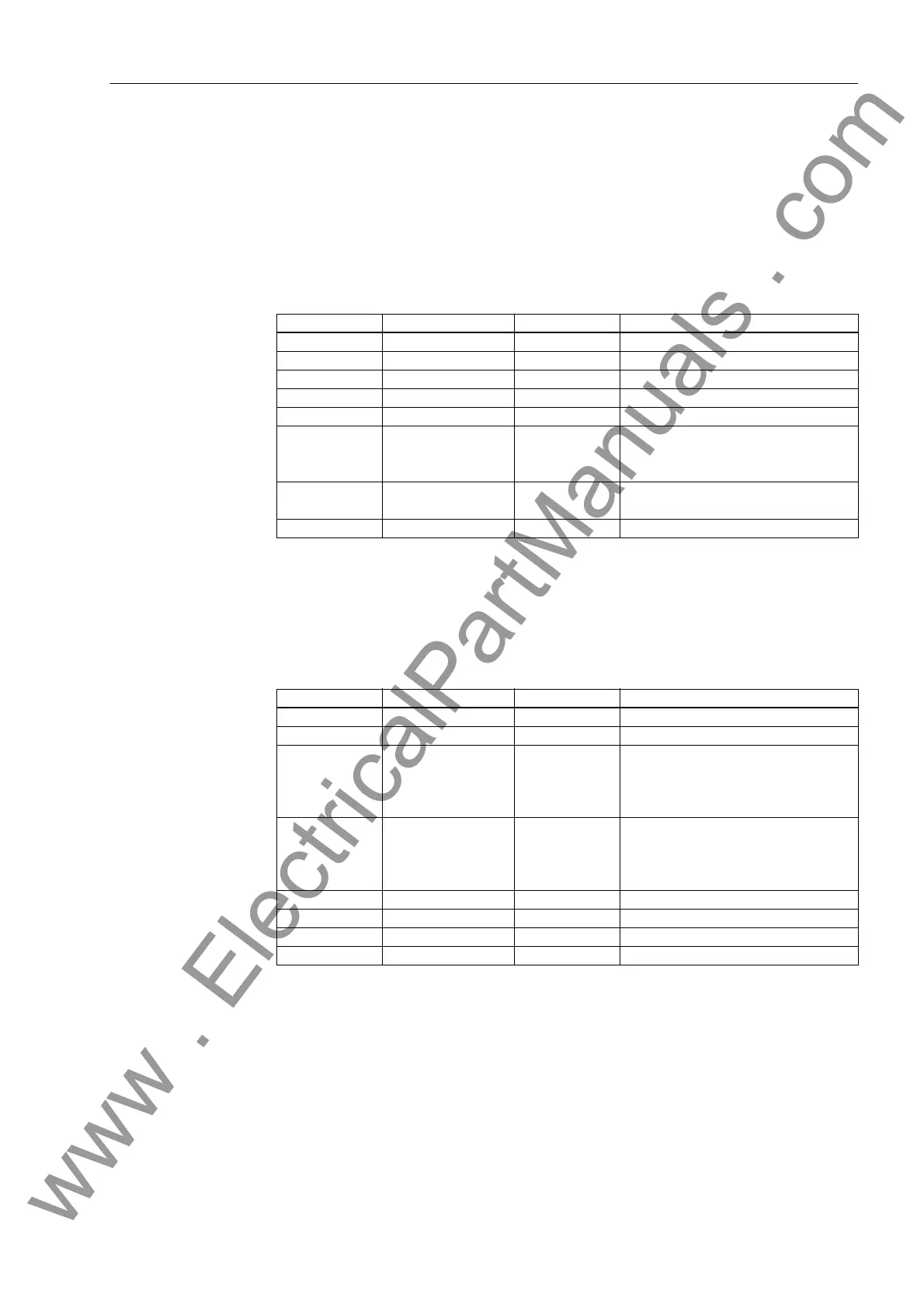
A.4.1 LEDs
Table A-1 LED indication presettings
1)
Only for 7UM612
A.4.2 Binary Input
Table A-2 Binary input presettings for all devices and ordering variants
1)
Only Busbar Connection
2)
Only for 7UM612
LEDs Short Text Function No. Description
LED1 Relay TRIP 511 Relay GENERAL TRIP command
LED2 Relay PICKUP 501 Relay PICKUP
LED3 I> Fault L1 1811 O/C fault detection stage I> phase L1
LED4 I> Fault L2 1812 O/C fault detection stage I> phase L2
LED5 I> Fault L3 1813 O/C fault detection stage I> phase L3
LED6 IEE> TRIP 1226 IEE> TRIP
U0> TRIP 5187 Stator earth fault: U0 stage TRIP
S/E/F TRIP 5193 Stator earth fault protection TRIP
LED7 Error PwrSupply 147 Error Power Supply
Fail Battery 177 Failure: Battery empty
LED8 List Empty - -
1
Binary Input Short Text Function No. Description
BI1 >SV tripped 5086 >Stop valve tripped
BI2 >Uexc fail. 5328 >Exc. voltage failure recognized
BI3 >BLOCK f1 5206 >BLOCK stage f1
>BLOCK U< 6506 >BLOCK undervoltage protection U<
>S/E/F Iee off 5176 >Switch off earth current de-
tec.(S/E/F)
1
BI4 >FAIL:Feeder VT 361 >Failure: Feeder VT (MCB tripped)
>Useal-in BLK 1950 >O/C prot. : BLOCK undervoltage
seal-in
>BLOCK U/V 6503 >BLOCK undervoltage protection
BI5 >Ext trip 1 4526 >Trigger external trip 1
BI6 >Ext trip 2 4546 >Trigger external trip 2
BI7 >Trig.Wave.Cap. 4 >Trigger Waveform Capture
BI8 ... 14 List Empty - -
2
www . ElectricalPartManuals . com

 Loading...


