4 Technical Data
306
7UM61 Manual
C53000-G1176-C127-3
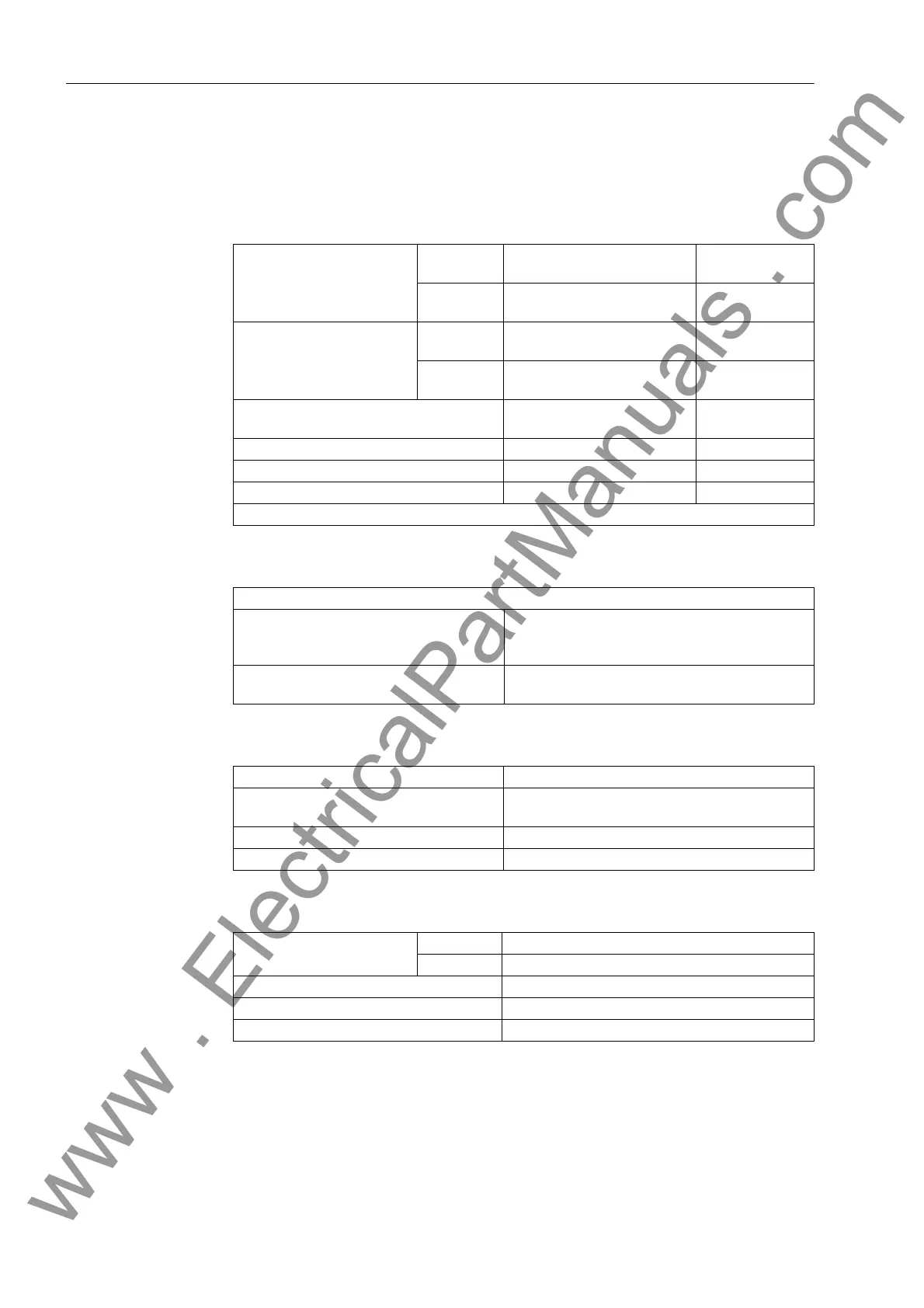
4.2 Definite-Time Overcurrent Protection (I>, ANSI 50/51; I>>, ANSI
50/51/67)
Setting Ranges / Increments
Times
Dropout Ratio
Tolerances
Pickup Current I> for I
N
= 1 A 0.05 A to 20.00 A Increments
0.01 A
for I
N
= 5 A 0.25 A to 100.00 A Increments
0.05 A
Pickup Current I>> for I
N
= 1 A 0.05 A to 20.00 A Increments
0.01 A
for I
N
= 5 A 0.25 A to 100.00 A Increments
0.05 A
Delay times T 0.00 s to 60.00 s
or ∞ (ineffective)
Increments 0.01 s
Undervoltage Seal-In U (phase-to-phase) 10.0 V to 125.0 V Increments 0.01V
Holding Time of Undervoltage Seal-In 0.10 s to 60.00 s Increments 0.01 s
Directional limit line angle tolerance I>> –90° el. to +90° el. Increments 1°
The set times are pure delay times.
Pickup times (without inrush restraint, with restraint add 10 ms)
I >, I>>
Current = 2 × Pickup Value
Current = 10 × Pickup Value
approx. 35 ms
approx. 25 ms
Dropout Times
I >, I>>
.
approx. 50 ms
Dropout ratio overcurrent I> approx. 0.95 for I/I
N
≥ 0.3
Dropout ratio overcurrent I>> 0.90 to 0.99
(Increments 0.01)
Dropout ratio undervoltage approx. 1.05
Dropout difference ∆ϕ 2 ° electrical
Pickup current I>, I>> for I
N
= 1 A 1 % of setting value or 10 mA
for I
N
= 5 A 5 % of setting value or 50 mA
Undervoltage Seal-In U< 1 % of setting value or 0.5 V
Delay times T 1 % or 10 ms
Directional limit lines angle 1° electrical
www . ElectricalPartManuals . com

 Loading...


