2.8 Inverse-Time Overcurrent Protection (ANSI 51V)
53
7UM61 Manual
C53000-G1176-C127-3
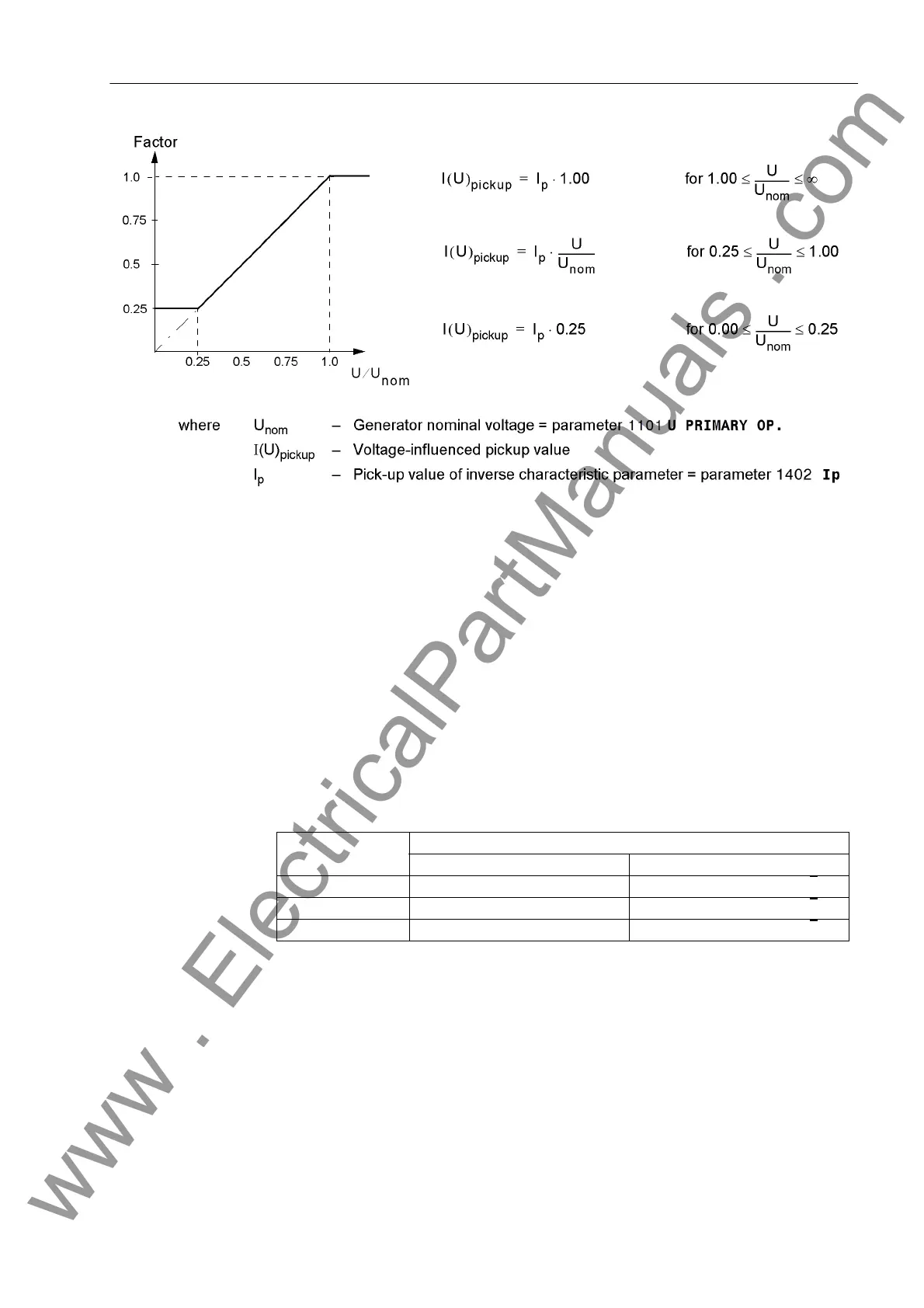
Figure 2-10 Pick-up Value Voltage Dependency
The Ip reference value is decreased proportional to voltage decrease. Consequently
for constant current I, the I/Ip ratio is increased and the trip time is reduced. Compared
with the standard characteristics represented in Section 4 the tripping characteristic
shifts to the left side in relation to decreasing voltage.
The changeover to the lower pick-up value or the reduction of the pickup threshold are
performed on a per phase basis. Allocations of voltages to the current-carrying phases
represented in the following table apply. As the protection used in the generator range
is incorporated in the network grading plan, conversion of the voltages by the unit
transformer must also be considered. Therefore in principle a distinction must be
made between a unit connection and a busbar connection which must be communi-
cated to the device by the parameter 272 SCHEME. As phase-to-phase voltages are
referred to in any case, faulty measurements during earth faults are avoided.
Table 2-3 Controlling voltages in relation to the fault currents
In or to avoid unwanted operation during a voltage transformer fault, a function block-
ing is implemented via a binary input controlled by the voltage transformer protective
breaker as well as via the device-internal measuring voltages failure detection (“Fuse–
Failure–Monitor”, also refer to Section 2.28).
The following figure shows the logic diagram of the inverse overcurrent time protection
without undervoltage influencing, whereas Figures 2-12 and 2-13 illustrate the logic di-
agrams with undervoltage influencing.
Current Voltage
Busbar connection Unit connection
I
L1
U
L1
– U
L2
((U
L1
– U
L2
) – (U
L3
– U
L1
)) / √3
I
L2
U
L2
– U
L3
((U
L2
– U
L3
) – (U
L1
– U
L2
)) / √3
I
L3
U
L3
– U
L1
((U
L3
– U
L1
) – (U
L2
– U
L3
)) / √3
www . ElectricalPartManuals . com

 Loading...


