2.36 Command Processing
227
7UM61 Manual
C53000-G1176-C127-3
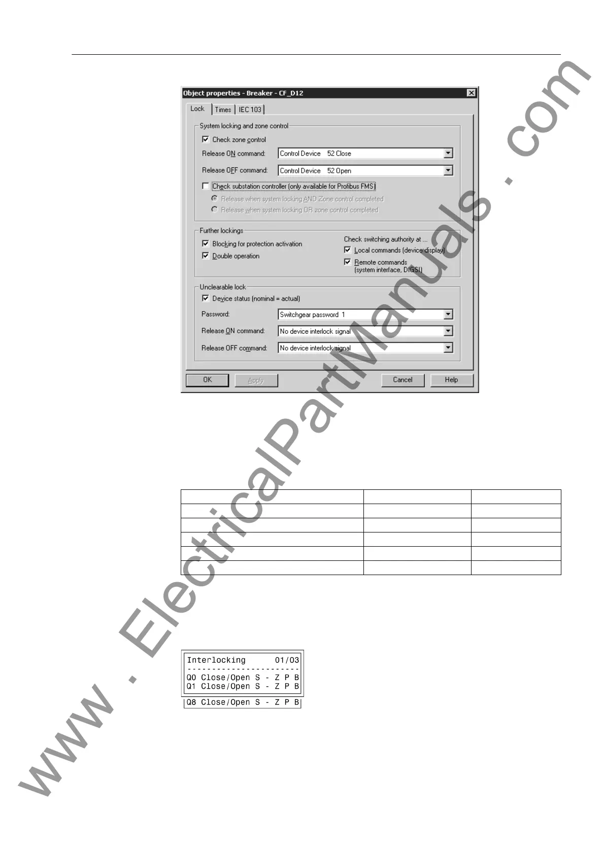
Figure 2-83 DIGSI
®
–dialog box for setting the interlocking conditions
For devices with operator panel the display shows the configured interlocking reasons.
They are marked by letters explained in the following table.
Table 2-14 Command types and corresponding messages
The following figure shows all interlocking conditions (which usually appear in the
display of the device) for three switchgear items with the relevant abbreviations ex-
plained in the previous table. All parameterized interlocking conditions are indicated.
Figure 2-84 Example of configured interlocking conditions
Interlocking Commands Abbrev. Message
Switching authority L L
System interlocking S S
Zone controlled Z Z
SET= ACTUAL (switch direction check) P P
Protection blockage B B
www . ElectricalPartManuals . com

 Loading...


