3.1 Mounting and Connections
235
7UM61 Manual
C53000-G1176-C127-3
The factor 213 FACTOR IEE considers the transformation ratio between the primary
and the secondary side of the summation current transformer when using the sensitive
current input in the corresponding connection example.
Example:
Summation current transformer 60 A / 1 A
Matching factor for sensitive earth fault current detection: FACTOR IEE = 60
In the appendix “the busbar system with low-ohmic earthing” is low-ohmic earthed at
the generator starpoint. To avoid circulating currents (3rd harmonic) in multi-generator
connections, the resistor should be connected to only one generator. For selective
earth fault detection, the sensitive earth fault current input I
EE
is looped into the
common return line of the two sets of CTs (current differential measurement). The
current transformers are earthed in one place only. FACTOR IEE is set to 1. Balanced
DE current transformers (winding balance) are recommended for this type of circuit.
In the appendix the “unit connection example with isolated starpoint”, earth fault de-
tection uses the displacement voltage. A load resistor is provided on the broken delta
winding to avoid spurious tripping during earth faults in the power system. The U
E
input of the device is connected via a voltage divider to the broken delta winding of an
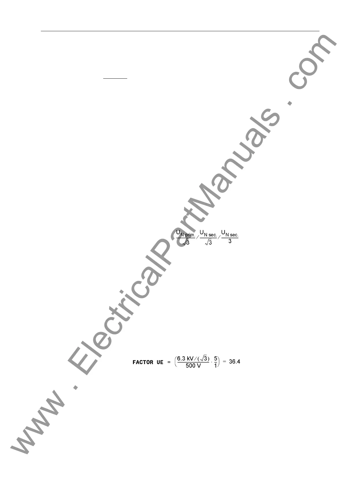
earthing transformer (address 223 UE CONNECTION = broken delta). Factor 225
Uph / Udelta is determined by the transformation ratio of the secondary-side volt-
ages:
The resulting factor between the secondary windings is 3/√3 = 1.73. For other trans-
formation ratios e.g. where the displacement voltage is measured using an inserted
CT set, the factor must be modified accordingly.
The factor 224 FACTOR UE considers the transformation full ratio between the primary
voltage and the voltage fed to the device terminals, i.e. it includes the voltage divider
that is connected upstream. For a primary nominal transformer voltage of 6.3 kV, a
secondary voltage of 500 V with full displacement and a voltage divider ratio of 1:5,
this factor would be for example
Instructions - see section 2.3 under "Transformation ratio CTR
E
".
In the “unit connection with neutral transformer” example, in the appendix, a load re-
sistor connected to the generator starpoint reduces the interference voltage from
network-side earth faults. The maximum earth fault current is limited to approx. 10A.
The resistor can be a primary or secondary resistor with neutral transformer. The
neutral transformer should have a low transformation ratio to avoid a small secondary
www . ElectricalPartManuals . com

 Loading...


