3.1 Mounting and Connections
247
7UM61 Manual
C53000-G1176-C127-3
C-I/O-2 Input /
Output Module
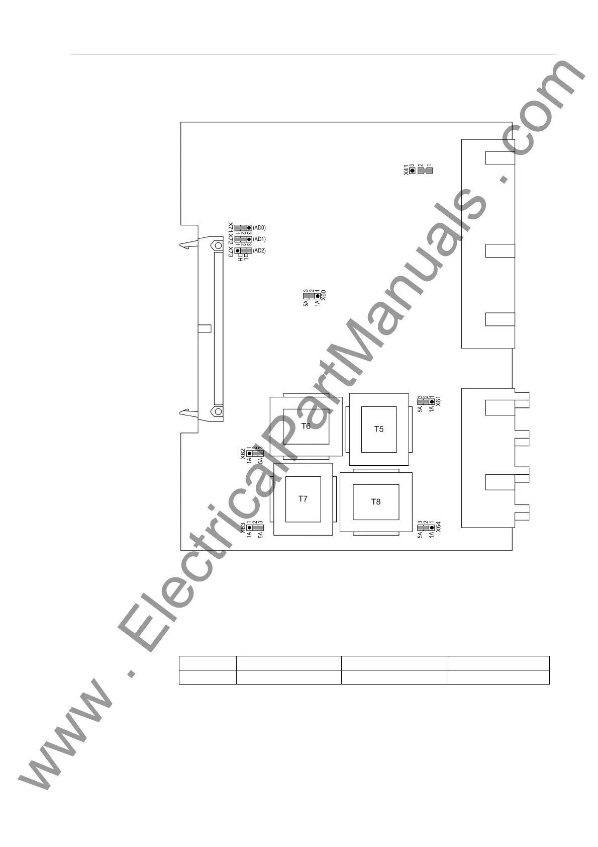
PCB layout for the C-I/O-2 board is shown in the following Figure.
Figure 3-6 Input/output board C–I/O-2 with representation of jumper settings required for
checking configuration settings
The relay contact for binary output BO17 can be configured as normally open or nor-
mally closed (see overview diagrams in Appendix A.2):
Table 3-10 Jumper Setting for Relay Contact for Binary Output BO17
Jumper Normally open contactor Normally closed contact Presetting
X41 1–2 2–3 1–2
www . ElectricalPartManuals . com

 Loading...


