3.3 Commissioning
275
7UM61 Manual
C53000-G1176-C127-3
Amplitudes Read out voltages in all three phases in the operational measured values and
compare with the actual voltages. The voltage of the positive sequence system U
1
must be approximately the same as the indicated phase voltages. If there are signifi-
cant deviations, the voltage transformer connections are incorrect.
P h a s e R o t a t i o n The phase rotation must conform with the configured phase sequence (address 271
PHASE SEQ. under Power System Data 1); otherwise an indication “Fail Ph.
Seq.” will be output. The allocation of measured values to phases must be checked
and corrected, if necessary. If signification deviations are found, check, and if neces-
sary correct, the voltage transformer circuits and repeat the test. It is also possible to
use for this check the operational measured value of positive-sequence component
U1 of the voltages: With U
1
≠ U
L-E
a wiring error is indicated.
Measuring Circuit
Supervision of the
Rotor Earth Fault
Protection
If the sensitive earth fault protection is used for rotor earth fault protection, the mea-
suring circuit supervision of that protection function can be checked with the generator
under voltage:
• Start up the generator and excite it to rated voltage. Apply measurement brushes if
necessary. Inject a test voltage between the rotor circuit and the earth by interpos-
ing the additional source device 7XR61. The earth current I
EE
that is flowing now
can be read out on the device under the earth fault measured values. The value ob-
tained is the capacitive spill current flowing in fault-free operation.
• IEE< (address 5106) should be set to about 50 % of this capacitive spill current. It
should also be checked that the set value IEE> (address 5102) is at least twice this
measured spill current. Correct the set value if necessary.
Frequency The frequency protection function is verified by a plausibility check of the instanta-
neous machine speed and the operational measured value indicated.
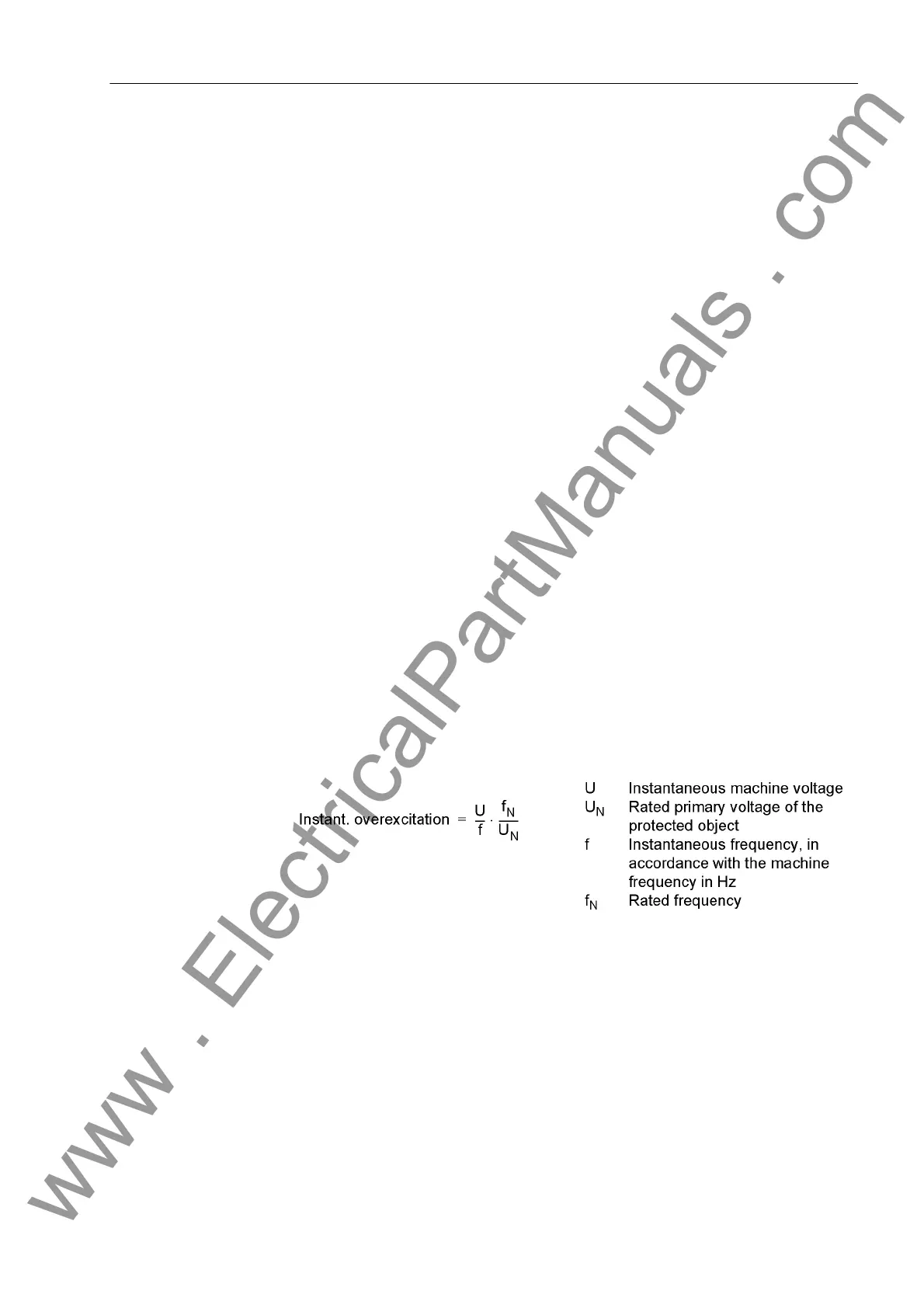
O v e r e x c i t a t i o n The frequency protection function is verified by a plausibility check of the instanta-
neous machine speed and the operational measured value indicated.
The voltage tests are completed after the generator has been shut down. The required
voltage and frequency protection functions are activated (address 4001:
UNDERVOLTAGE = ON or OFF, address 4101: OVERVOLTAGE = ON or OFF, address
4201: O/U FREQUENCY = ON or OFF, address 4301: OVEREXC. PROT. = ON or
OFF). Partial functions can be disabled by appropriate limit value settings (e.g. fre-
quency set to f
Nom
).
www . ElectricalPartManuals . com

 Loading...


