2.14 Impedance Protection (ANSI 21)
93
7UM61 Manual
C53000-G1176-C127-3
Loop Selection
• The corresponding phase-earth loop is used for a 1-pole pickup.
• With a 2-pole pickup, the phase-phase loop with the corresponding phase-to-phase
voltage is used for impedance calculation.
• With a 3-pole pickup, the phase-phase loop with the highest current value is used
and with equal current amplitudes, the procedure described in the last row of the
following of table is applied.
Table 2-5 Measuring Loop Selection
This loop selection type ensures that the fault impedance of system faults is measured
correctly via the unit transformer. A measuring error occurs with a 1-pole system short-
circuit, since the zero phase-sequence system is not transmitted via the machine
transformer (switching group e.g. Yd5). The following table describes the fault model-
ing and the measuring errors.
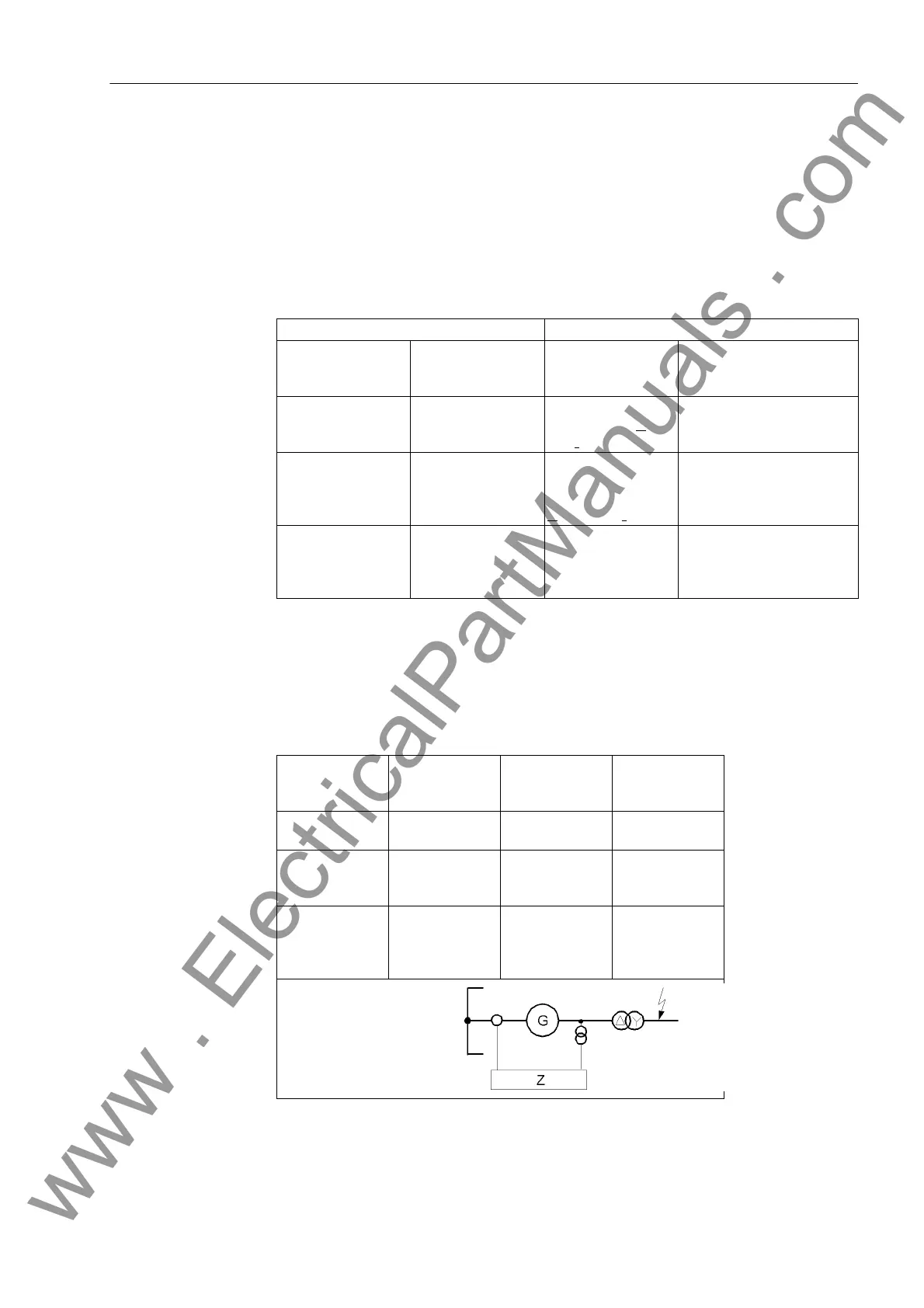
Table 2-6 Fault Modeling and Measuring Errors on the Generator Side on System Faults
Pickup Measuring Loop
1-pole L1
L2
L3
Phase-earth L1–E
L2–E
L3–E
2-pole L1, L2
L2, L3
L3, L1
Phase-phase,
Calculation of U
I I
and I
I I
L1– L2
L2– L3
L3– L1
3-pole,
with different ampli-
tudes
L1,2*L2,L3
L2.2*L3,L1
L3.2*L2,L3
Phase-ground, se-
lection of loop with
the highest current
U
I (Imax)
and I
I (Imax)
L2–E
L3–E
L1–E
3-pole,
with equal ampli-
tudes
L1, L2, L3 Phase-earth, any,
maximum current
amount
L1=IL2=IL3 then IL1
IL1=IL2 > IL3 then IL1
IL2=IL3 > IL1 then IL2
IL3=IL1 > IL2 then IL1
System Faults Fault Model on
the Generator
Side
Loop Selection Measuring
Errors
3–pole short
circuit
3–pole short
circuit
Phase-earth always correct
measurement
2–pole short
circuit
3–pole short
circuit
Phase-earth loop
with highest
current
always correct
measurement
1–pole short
circuit
2–pole short
circuit
Phase-phase
loop
Impedance mea-
sured too high by
the zero imped-
ance
www . ElectricalPartManuals . com

 Loading...


