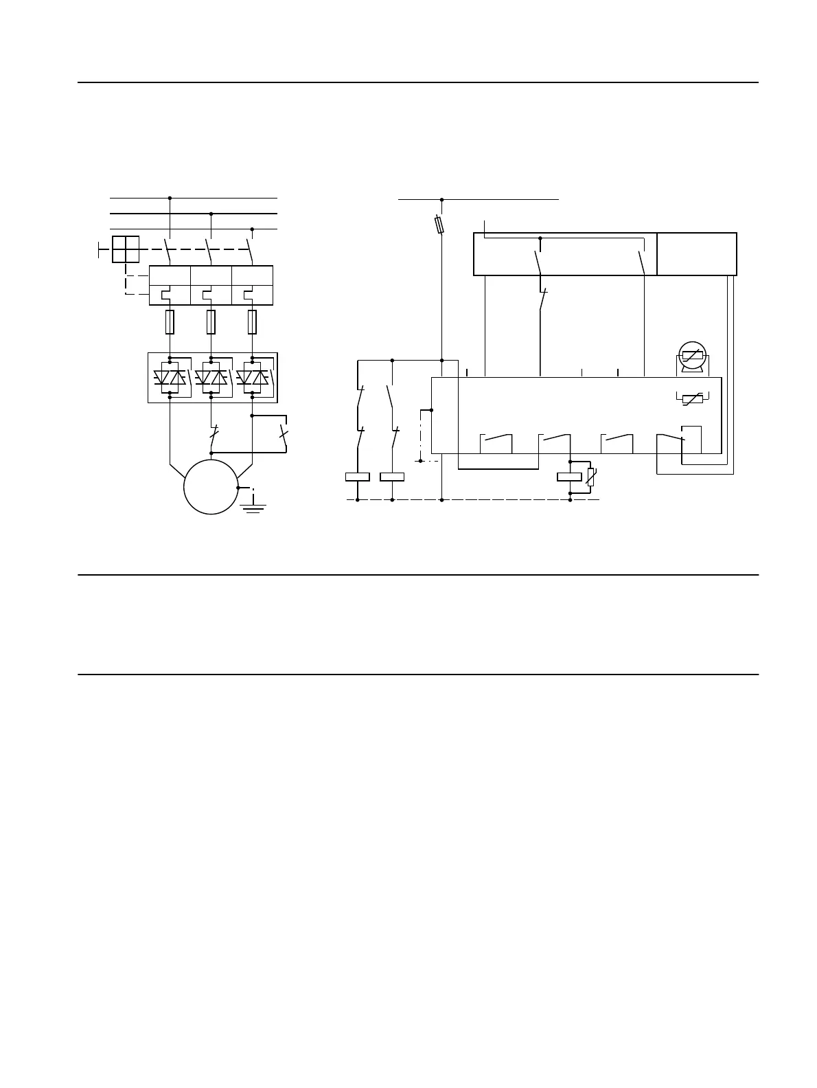
Circuit Examples
SIRIUS 3RW44 manual
GWA 4NEB 535 2195-02 DS 06
9-5
9.1.4 3RW44 in a Standard Circuit and DC Braking
3)
Stopping Function for Device Types 3RW44 26
to 3RW44 66
1) For permissible main and control voltage values, refer to Technical Data, pages 10-12 to 10-16.
2)
2) Caution: risk of restart!
The start command (e.g. by the PLC) must be reset before a reset command is issued, since an automatic
restart is executed when a start command is pending after the reset command is issued. This particularly
applies to motor protection tripping. For safety reasons, we recommend integrating the group error output
(terminals 95 and 96) into the control.
3) If the "Combined braking" stopping function is selected, no braking contactor is required.
If the "DC braking" function is selected, a braking contactor must be additionally used. For types, refer to
the "Branch component layout (standard circuit)" table on page
10-21.
The "DC braking" function is recommended for applications with larger centrifugal masses (J
load
> J
motor
).
Output 2 must be set to "DC braking contactor".
4) K4 auxiliary relay, e.g.:
LZX:RT4A4T30 (230 V AC rated control supply voltage),
LZX:RT4A4S15 (115 V AC rated control supply voltage).
Main circuit Control circuit
13(9$&
+]
4
)
4
4 4
0
3(
0
a
/
/
/
/ / /
7 7 7
8:
9
6,725
I >> I >> I >>
RSWLRQ
16%B
$
1
3(
3(
/ / ,1 ,1 ,1 ,1 7 7
4
.
..
)
$
8
4
4
4
4
.
0
/
13(9$&
+]
16%BE
˽
˽
1RDFWLRQ
1RDFWLRQ
5HVHW
1R
DFWLRQ
*URXSHUURU
2Q
WLPH
37&W\SH$
RU
7KHUPRFOLFN
6WDUW
0RWRUULJKW
3/&LQSXWV3/&RXWSXWV
'&EUDNH
FRQWDFWRU
36

 Loading...


