General Technical Data
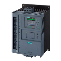
SIRIUS 3RW44 manual
GWA 4NEB 535 2195-02 DS 06
10-19
10.3.4 Conductor Cross-Sections
1) When connecting cable lugs according to DIN 46235 from a conductor cross-section of 95 mm², the 3RT19 56-4EA1 terminal cover is required to ensure phase clearance.
2) When connecting cable lugs according to DIN 46234 from a conductor cross-section of 240 mm² as well as DIN 46235 from a conductor cross-section of 185 mm², the 3RT19 66-4EA1
terminal cover is required to ensure phase clearance.
Type 3RW44 2 . 3RW44 3. 3RW44 4. 3RW44 5.
3RW44 6 .
Conductor cross-sections
Screw-type terminals Main conductor:
With box terminal 3RT19 55-4G (55 kW) 3RT19 66-4G —
Front terminal
connected
• Finely stranded with cable end sleeve mm
2
2.5 ... 35 16 ... 70 70 ... 240 —
• Finely stranded without cable end sleeve mm
2
4...50 16 ... 70 70 ... 240 —
•Solid mm
2
2.5 ... 16 — — —
• Stranded mm
2
4...70 16 ... 70 95 ... 300 —
• Ribbon cable (number x width x thickness) mm
6x9x0.8 min.3x9x0.8,
max. 6 x 15.5 x 0.8
min. 6 x 9 x 0.8
max. 20 x 24 x 0.5
—
• AWG conductors, solid or stranded AWG
10 ... 2/0 6...2/0 3/0 ... 600 kcmil —
Rear terminal connected • Finely stranded with cable end sleeve mm
2
2.5 ... 50 16 ... 70 120 ... 185 —
• Finely stranded without cable end sleeve mm
2
10 ... 50 16 ... 70 120 ... 185 —
•Solid mm
2
2.5 ... 16 — — —
• Stranded mm
2
10 ... 70 16 ... 70 120 ... 240 —
• Ribbon cable (number x width x thickness) mm
6x9x0.8 min.3x9x0.8,
max. 6 x 15.5 x 0.8
min. 6 x 9 x 0.8
max. 20 x 24 x 0.5
—
• AWG conductors, solid or stranded AWG
10 ... 2/0 6...2/0 250 ... 500 kcmil —
Both terminals
connected
• Finely stranded with cable end sleeve mm
2
2x(2.5...35) max. 1x50, 1x70 min. 2 x 50;
max. 2 x 185
—
• Finely stranded without cable end sleeve mm
2
2x(4...35) max. 1x50, 1x70 min. 2 x 50;
max. 2 x 185
—
•Solid mm
2
2x(2.5...16) — — —
• Stranded mm
2
2x(4...50) max. 2 x 70 max. 2 x 70;
max. 2 x 240
—
• Ribbon cable (number x width x thickness) mm
2x(6x9x0.8) max. 2 x
(6 x 15.5 x 0.8)
max. 2 x
(20 x 24 x 0.5)
—
• AWG conductors, solid or stranded AWG
2x(10...1/0) max. 2 x 1/0 min. 2 x 2/0;
max. 2 x 500 kcmil
—
• Connecting screws
M6 (hexagon socket, A/
F4)
M10 (hexagon socket,
A/F4)
M12 (hexagon socket,
A/F5)
—
- Tightening torque Nm
4...6 10 ... 12 20 ... 22 —
lbf.in
36 ... 53 90 ... 110 180 ... 195 —
Screw-type terminals Main conductor:
With box terminal — 3RT19 56-4G — —
Front or rear terminal
connected
• Finely stranded with cable end sleeve mm
2
— 16 ... 120 — —
• Finely stranded without cable end sleeve mm
2
— 16 ... 120 — —
• Stranded mm
2
— 16 ... 120 — —
• Ribbon cable (number x width x thickness) mm
— min.3x9x0.8
max. 6 x 15.5 x 0.8
— —
• AWG conductors, solid or stranded AWG
— 6 ... 250 kcmil — —
Both terminals
connected
• Finely stranded with cable end sleeve mm
2
— max. 1x95, 1x120 — —
• Finely stranded without cable end sleeve mm
2
— max. 1x95, 1x120 — —
• Stranded mm
2
— max. 2 x 120 — —
• Ribbon cable (number x width x thickness) mm
— max. 2 x
(10x15.5x0.8)
— —
• AWG conductors, solid or stranded AWG
— max. 2 x 3/0 — —
Screw-type terminals Main conductor:
Without box terminal / busbar connections
• Finely stranded with cable lug mm
2
— 16 ... 95
1)
50 ... 240
2)
50 ... 240
2)
• Stranded with cable lug mm
2
— 25 ... 120
1)
70 ... 240
2)
70 ... 240
2)
• AWG conductors, solid or stranded AWG — 4 ... 250 kcmil 2/0 ... 500 kcmil 2/0 ... 500 kcmil
• Connecting bar (max. width) mm
— 17 25 60
• Connecting screws
— M8 x 25 (A/F13) M10 x 30 (A/F17) M12 x 40
- Tightening torque Nm
— 10 ... 14 14 ... 24 20 ... 35
lbf.in
— 89 ... 124 124 ... 210 177 ... 310

 Loading...

