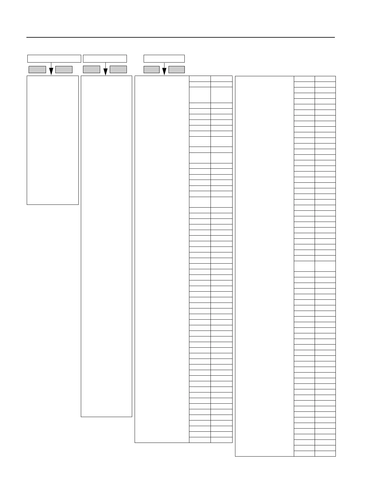
10.1 Menu Structure
** Possible only in connection with creep speed
Device status
Active parameter set
Parameter set 1
Parameter set 2
Parameter set 3
Type of connection
Unknown/faulty
Star/delta
Inside delta
Direction of rotation
Unknown
Clockwise
Counter-clockwise
Inputs
Status - Inputs
Input 1 - Action
No action
Manual operation
local
Emergency start
Slow speed
Quick stop
Trip reset
Motor right PS1
Motor left PS1 **
Motor right PS2
Motor left PS2 **
Motor right PS3
Motor left PS3 **
Input 2 - Action [...]
Input 3 - Action [...]
Input 4 - Action [...]
Outputs
Status - Outputs
Output 1 - Action
No action
PIO output 1
PIO output 2
Input 1
Input 2
Input 3
Input 4
Run up
Bypass operation
Coasting down
On-time motor
Command motor-on
DC braking contactor
Group warning
Group error
Bus error
Device errors
Power on
Ready to start
Output 2 - Action [...]
Output 3 - Action [...]
Output 4 - Action [...]
Order number
Firmware information
Version
Date
Display measured value
OKESC
Status display
OKESC
Parameter set 1
Motor 1
Rated operating current Ie
Depends on
order
number
Rated operating torque 0
Rated operating speed 1,500
Copy motor data to PS2 + 3
Starting settings
Starting mode
Voltage ramp
Voltage ramp + current
limiting
x
Torque control
Torque control + current
limiting
Direct on line
Motor heating
Start voltage 30 %
Start torque 10 %
Limiting torque 150 %
Starting time 10 s
Maximum starting time 0/
deactivated
Current limiting value 400 %
Breakaway voltage 40 %
Breakaway time 0 ms
Motor thermal capacity 20 %
Stopping settings
Stopping mode
Coasting down x
Torque control
Pump stop
DC braking
Combined braking
Stopping time 10 s
Stopping torque 10 %
Dynamic braking torque 50 %
DC braking torque 50 %
Slow speed parameters
Slow speed factor right 7
Slow speed torque right 50 %
Slow speed factor left 7
Slow speed torque left 50 %
Current limit values
Minimum current limit value 18.75 %
Maximum current limit value 112.50 %
Parameter set 2 [...]
Parameter set 3 [...]
Inputs
Input 1 - Action
No action
Manual operation local
Emergency start
Slow speed
Quickstop
Trip Reset
Motor right PS1 x
Motor left PS1 **
Motor right PS2
Motor left PS2 **
Motor right PS3
Motor left PS3 **
Input 2 - Action [...] No Action
Input 3 - Action [...] No Action
Input 4 - Action [...] Trip Reset
Settings
OKESC
Factory
Settings
Phase voltages
UL1N
UL2N
UL3N
Phase-to-phase voltages
UL1-L2
UL2-L3
UL3-L1
Blocking voltages
ULT1
ULT2
ULT3
Phase currents
IL1
IL2
IL3
Power
Line frequency
Supply voltage
Heatsink temperature
Motor heat build-up
Remaining time for tripping
Switch off standard display
Customer
Settings
Outputs
Output 1 - Action
No action
PIO output 1
PIO output 2
Input 1
Input 2
Input 3
Input 4
Run up
Operation / bypass
Coasting down
On-time motor x
Command motor-on
DC braking contactor
Group warning
Group error
Bus error
Device errors
Power on
Ready to start
Output 2 - Action [...] No Action
Output 3 - Action [...] No Action
Motor protection
Tripping class
None
CLASS 5 (10a)
CLASS 10 x
CLASS 15
CLASS 20
CLASS 30
Current asymmetry limit value 40 %
Prewarning limit tripping reserve 0 s
Prewarning limit motor heat
build-up
80 %
Idle time 0 s
Pre-charge time 60 s
Protection against voltage failure
No
Ye s x
Temperature sensor
Deactivated x
Thermo click
PTC-type A
Display settings
Language
English x
Deutsch
Français
Español
Italiano
Português
Nederlands
Ελληνικά
Türkçe
Русский
中文
Contrast 50 %
Lighting
Brightness
Lighting on x
Off with time delay
Lighting off
Response to fault
Unchanged
On
Blinking
Flickering x
Factory
Settings
Customer
Settings

 Loading...


