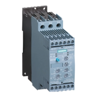
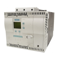
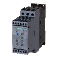
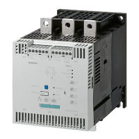
General Technical Data
SIRIUS 3RW44 manual
GWA 4NEB 535 2195-02 DS 06
10-23
1) If the "Combined braking" stopping function is selected, no braking contactor is required.
If the "DC braking" function is selected, a braking contactor must be additionally used (for type, see table).
The "DC braking" function is recommended for applications with larger centrifugal masses (J
load
> J
motor
).
2) Additional K4 auxiliary relay:
LZX:RT4A4T30
(3RW44 soft starter with 230 V AC rated control supply voltage),
LZX:RT4A4S15
(3RW44 soft starter with 115 V AC rated control supply voltage).
3) "Utilization class 2" refers to the soft starter in combination with the protective device listed (circuit breaker/fuse), not to
other components in the branch. For utilization class, see page 10-20.
Standard circuit fused design with SITOR 3NE1 all-range fuse (semiconductor and line protection)
For suitable fuse bases, see LV1 catalog at
"SENTRON Switching and Protection Devices for Power Distribution" –> "Switch Disconnectors"
and ET B1 Catalog at "BETA Protecting" –> "SITOR Semiconductor Fuses"
and/or at www.siemens.com/sitor
> SITOR Semiconductor Fuses
Soft starters All-range fuse Line contactor up to
400 V
Braking contactor
1)2)
Nominal
current
Rated current Voltage Size (option) (circuit suggestions from page 9-2)
Q11 E’1 Q21 Q91 Q92
Type A Type A V Type Type Type
Utilization class 2
3)
: I
q
=65kA
3RW44 22 29 3NE1 020-2 80 690 +5 % 00 3RT10 34 3RT15 26 —
3RW44 23 36 3NE1 020-2 80 690 +5 % 00 3RT10 35 3RT15 26 —
3RW44 24 47 3NE1 021-2 100 690 +5 % 00 3RT10 36 3RT15 35 —
3RW44 25 57 3NE1 022-2 125 690 +5 % 00 3RT10 44 3RT15 35 —
3RW44 26 77 3NE1 022-2 125 690 +5 % 00 3RT10 45 3RT10 24 3RT10 35
3RW44 27 93 3NE1 024-2 160 690 +5 % 1 3RT10 46 3RT10 25 3RT10 36
3RW44 34 113 3NE1 225-2 200 690 +5 % 1 3RT10 54 3RT10 34 3RT10 44
3RW44 35 134 3NE1 227-2 250 690 +5 % 1 3RT10 55 3RT10 36 3RT10 45
3RW44 36 162 3NE1 227-2 250 690 +5 % 1 3RT10 56 3RT10 44 3RT10 45
3RW44 43 203 3NE1 230-2 315 600 +10 % 1 3RT10 64 3RT10 44 3RT10 54
3RW44 44 250 3NE1 331-2 350 460 +10 % 2 3RT10 65 3RT10 44 3RT10 55
3RW44 45 313 3NE1 333-2 450 690 +5 % 2 3RT10 75 3RT10 54 3RT10 56
3RW44 46 356 3NE1 334-2 500 690 +5 % 2 3RT10 75 3RT10 54 3RT10 56
3RW44 47 432 3NE1 435-2 560 690 +5 % 3 3RT10 76 3RT10 55 3RT10 64
3RW44 53 551 2 x 3NE1 334-2 500 690 +10 % 2 3TF68 44-0CM7 3RT10 64 3RT10 66
3RW44 54 615 2 x 3NE1 334-2 500 690 +10 % 2 3TF68 44-0CM7 3RT10 64 3RT10 75
3RW44 55 693 2 x 3NE1 334-2 500 690 +10 % 2 3TF69 44-0CM7 3RT10 65 3RT10 75
3RW44 56 780 2 x 3NE1 435-2 560 690 +10 % 3 3TF69 44-0CM7 3RT10 65 3RT10 75
3RW44 57 880 2 x 3NE1 435-2 560 690 +10 % 3 —2 x 3TF69 44-0CM7 3RT10 75 3RT10 76
3RW44 58 970 2 x 3NE1 435-2 560 690 +10 % 3 — 3RT10 75 3RT10 76
3RW44 65 1076 3 x 3NE1 334-2 500 690 +10 % 2 — 3RT10 75 3TF68
3RW44 66 1214 3 x 3NE1 435-2 560 690 +10 % 3 — 3RT10 76 3TF68
2
ToC

 Loading...

