Home
Siemens
DC Drives
SIROTEC
Siemens SIROTEC User Manual
4
of 1
of 1 rating
826 pages
Give review
Manual
Specs
To Next Page
To Next Page
To Previous Page
To Previous Page
Loading...
Line Modu
les Books
ize
4.6
Activ
e Line Modu
les Liquid
Cooled
Booksize Power Units
216
Manual
,
(GH2), 07/2016
,
6S
L3097
-
4AC00
-
0
BP8
4.6.3
Connectio
n example
Figure
4-
35
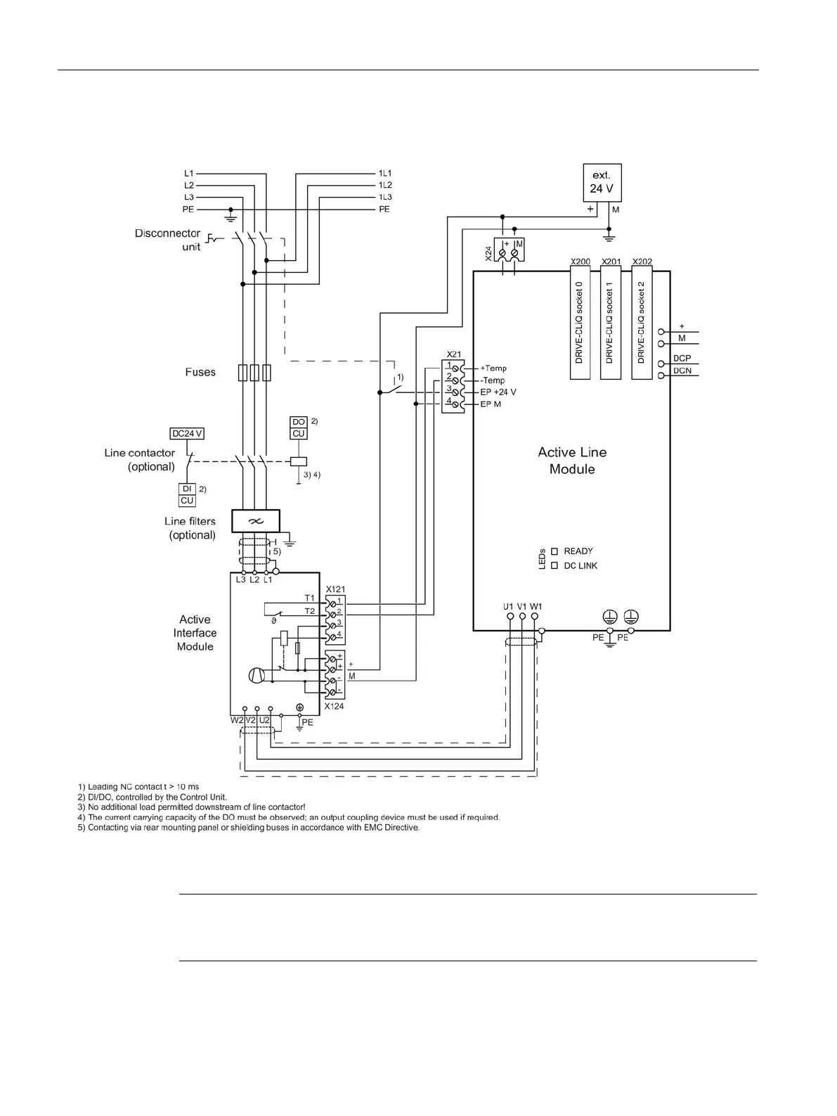
Example con
nection of A
ctive Line M
odule
Note
If you are
using
a VSM1
0 Voltage
Sensing Mo
dule, the
leading open
ing contac
t can be
omitted.
215
217
Table of Contents
Default Chapter
5
Preface
5
Table of Contents
13
1 Fundamental Safety Instructions
27
General Safety Instructions
27
Safety Instructions for Electromagnetic Fields (EMF)
31
Handling Electrostatic Sensitive Devices (ESD)
31
Industrial Security
32
Residual Risks of Power Drive Systems
34
2 System Overview
35
Field of Application
35
Platform Concept and Totally Integrated Automation
36
Introduction
38
SINAMICS S120 Components
40
Overview of Line Modules
43
Overview of Motor Modules
45
System Data
46
3 Line Connection and Line-Side Power Components
49
Introduction
49
Information on the Disconnector Unit
50
Overcurrent Protection by Means of Line Fuses and Circuit Breakers
51
Line Supply Connection Via Residual-Current Devices
53
Residual-Current Operated Circuit Breakers (RCD)
53
Residual-Current Monitors (RCM)
55
Overvoltage Protection
57
Line Contactors
57
Line Filters
58
Safety Instructions for Line Filters
58
Overview of Line Filters
60
Basic Line Filters for Active Line Modules
62
Description
62
Interface Description
63
Dimension Drawings
64
Technical Data
67
Wideband Line Filter for Active Line Modules
68
Description
68
Interface Description
69
Dimension Drawings
71
Technical Data
75
Basic Line Filter for Basic Line Modules
76
Description
76
Interface Description
77
Dimension Drawings
78
Technical Specifications
80
Basic Line Filter for Smart Line Modules
81
Description
81
Interface Description
82
Dimension Drawings
83
Technical Data
85
Line Reactors
86
Safety Instructions for Line Reactors
86
Overview of the Line Reactors
88
Line Reactors for Active Line Modules
89
Interface Description
89
Dimension Drawings
93
Technical Data
98
Damping Resistor for HFD Line Reactors
98
Description
98
Safety Instructions for Damping Resistors for HFD Reactors
99
Dimension Drawings
99
Technical Data
102
Wiring with the HFD Line Reactor
103
Line Reactors for Basic Line Modules
104
Interface Description
104
Dimension Drawings
106
Technical Data
109
Line Reactors for Smart Line Modules
109
Interface Description
109
Dimension Drawings
111
Technical Data
114
Active Interface Modules Internal Air Cooling
115
Description
115
Safety Instructions for Active Interface Modules
116
Interface Description
119
Overview
119
Line/Load Connection
123
X121 Temperature Sensor and Fan Control
123
X124 Electronics Power Supply
124
Connection Example
124
Dimension Drawings
125
Installation
129
Operation on an Isolated-Neutral System (IT System)
132
Electrical Tests
133
Technical Data
134
Combination Options, Line Modules with Line Reactors and Line Filters
135
Line Connection Variants
137
Ways of Connecting the Line Supply
137
Operating Line Connection Components on the Line Supply
138
Operation of the Line Connection Components Via a Transformer
139
Safety Instructions for Line Connection Components
139
Line Supply Connection Conditions for Line Modules
140
Dimensioning an Isolating Transformer / Autotransformer for Several Loads
141
Operating Line Connection Components Via an Autotransformer
146
Operating Line Connection Components Via an Isolating Transformer
147
4 Line Modules Booksize
149
Safety Instructions for Line Modules Booksize
149
Frequency with Which the DC Link Is Precharged
153
Active Line Modules with Internal Air Cooling
154
Description
154
Interface Description
155
Overview
155
X1 Line Connection
156
X12 Fan Connection
157
X21 EP Terminals
157
X24 24 V Terminal Adapter
158
X200-X202 DRIVE-Cliq Interfaces
159
Connection Example
160
Meaning of Leds
161
Dimension Drawings
162
Installation
166
Technical Data
168
Characteristics
171
Active Line Modules with External Air Cooling
173
Description
173
Interface Description
174
Overview
174
X1 Line Connection
175
X12 Fan Connection
176
X21 EP Terminals
176
X24 24 V Terminal Adapter
177
X200-X202 DRIVE-Cliq Interfaces
178
Connection Example
179
Meaning of Leds
180
Dimension Drawings
181
Installation
184
Mounting Examples
187
Technical Data
190
Characteristics
193
Active Line Modules with Cold Plate
195
Description
195
Interface Description
196
Overview
196
X1 Line Connection
197
X21 EP Terminals
198
X24 24 V Terminal Adapter
199
X200-X202 DRIVE-Cliq Interfaces
199
Connection Example
200
Meaning of Leds
201
Dimension Drawings
202
Mounting
204
Technical Data
207
Characteristics
209
Active Line Modules Liquid Cooled
211
Description
211
Interface Description
212
Overview
212
X1 Line Connection
213
X21 EP Terminals
213
X24 24 V Terminal Adapter
214
X200-X202 DRIVE-Cliq Interfaces
215
Connection Example
216
Meaning of Leds
217
Dimension Drawing
218
Installation
219
Technical Data
220
Characteristics
222
Basic Line Modules with Internal Air Cooling
223
Description
223
Interface Description
224
Overview
224
X1 Line Connection
225
X2 Braking Resistor Connection
226
X21 EP Terminals
227
X24 24 V Terminal Adapter
228
X200-X202 DRIVE-Cliq Interfaces
229
Connection Examples
230
Meaning of Leds
232
Dimension Drawings
233
Installation
236
Operation on an Isolated-Neutral System (IT System)
237
Technical Data
238
Characteristics
239
Basic Line Modules with Cold Plate
241
Description
241
Interface Description
242
Overview
242
X1 Line Connection
243
X2 Braking Resistor Connection
244
X21 EP Terminals
245
X24 24 V Terminal Adapter
246
X200-X202 DRIVE-Cliq Interfaces
247
Connection Examples
248
Meaning of Leds
250
Dimension Drawings
251
Mounting
254
Operation on an Isolated-Neutral System (IT System)
257
Technical Data
258
Characteristics
260
Smart Line Modules with Internal Air Cooling
261
Description
261
Additional Safety Instructions for Smart Line Modules Booksize
262
Switch-On/Switch-Off Sequence for 5 Kw and 10 Kw Smart Line Modules
263
Interface Description
264
Overview
264
X1 Line Connection
267
X21 EP Terminals
269
X22 Digital Inputs
272
X24 24 V Terminal Adapter
273
X200-X202 DRIVE-Cliq Interfaces
273
Connection Examples
274
Meaning of Leds
276
Smart Line Modules 5 Kw and 10 Kw
276
16 Kw to 55 Kw Smart Line Modules
277
Dimension Drawings
278
Installation
282
Technical Data
283
Characteristics
285
Smart Line Modules with External Air Cooling
286
Description
286
Additional Safety Instructions for Smart Line Modules Booksize
286
Switch-On/Switch-Off Sequence for 5 Kw and 10 Kw Smart Line Modules
287
Interface Description
288
Overview
288
X1 Line Connection
291
X21 EP Terminals
293
X22 Digital Inputs
296
X24 24 V Terminal Adapter
297
X200-X202 DRIVE-Cliq Interfaces
297
Connection Examples
298
Meaning of Leds
300
Smart Line Modules 5 Kw and 10 Kw
300
16 Kw to 55 Kw Smart Line Modules
300
Dimension Drawings
301
Mounting
305
Technical Data
310
Characteristics
312
Smart Line Modules with Cold Plate
313
Description
313
Additional Safety Instructions for Smart Line Modules Booksize
313
Switch-On/Switch-Off Sequence for 5 Kw and 10 Kw Smart Line Modules
314
Interface Description
315
Overview
315
X1 Line Connection
316
X21 EP Terminals
316
X22 Digital Inputs
318
X24 24 V Terminal Adapter
318
Connection Example
319
Meaning of Leds
320
Dimension Drawings
321
Mounting
322
Technical Data
324
Characteristics
326
Measuring the Heat Sink Temperature
327
5 Line Modules Booksize Compact
329
Frequency with Which the DC Link Is Precharged
329
Smart Line Modules Booksize Compact
329
Description
329
Safety Instructions for Smart Line Modules Booksize Compact
330
Interface Description
334
Overview
334
X1 Line Connection
335
X21 EP Terminals
335
X24 24 V Terminal Adapter
337
X200-X202 DRIVE-Cliq Interfaces
337
Connection Example
338
Meaning of the Leds
339
Dimension Drawing
340
Mounting
341
Technical Data
343
Characteristics
345
6 Motor Modules Booksize
347
Safety Instructions for Motor Modules Booksize
347
Motor Modules with Internal Air Cooling
351
Description
351
Interface Description
352
Overview
352
Motor and Brake Connection
354
X12 Fan Connection
357
X21/X22 EP Terminals/Temperature Sensor
357
X200-X203 DRIVE-Cliq Interface
358
Connection Examples
359
Meaning of Leds
361
Dimension Drawings
362
Installation
367
Technical Data
369
Single Motor Modules
369
Double Motor Modules
371
Characteristics
372
Technical Data for Motor Modules Booksize with 300% Overload
375
Single Motor Modules (300% Overload)
375
Double Motor Modules (300% Overload)
376
Characteristics for Motor Modules Booksize with 300% Overload
377
Motor Module with External Air Cooling
381
Description
381
Interface Description
382
Overview
382
Motor and Brake Connection
384
X12 Fan Connection
387
X21/X22 EP Terminals/Temperature Sensor
387
X200-X203 DRIVE-Cliq Interface
388
Connection Examples
389
Meaning of Leds
391
Dimension Drawings
392
Mounting
397
Technical Data
403
Single Motor Modules
403
Double Motor Modules
405
Characteristics
406
Technical Data for Motor Modules Booksize with 300% Overload
409
Single Motor Modules (300% Overload)
409
Double Motor Modules (300% Overload)
410
Characteristics for Motor Modules Booksize with 300% Overload
412
Motor Modules with Cold Plate
415
Description
415
Interface Description
416
Overview
416
Motor and Brake Connection
418
X21/X22 EP Terminals/Temperature Sensor
421
X200-X203 DRIVE-Cliq Interface
422
Connection Examples
423
Meaning of Leds
425
Dimension Drawings
426
Mounting
430
Technical Data
433
Single Motor Modules
433
Double Motor Modules
435
Characteristics
436
Technical Data for Motor Modules Booksize with 300% Overload
439
Single Motor Modules (300% Overload)
439
Double Motor Modules (300% Overload)
440
Characteristics for Motor Modules Booksize with 300% Overload
441
Motor Modules Liquid Cooled
444
Description
444
Interface Description
445
Overview
445
Motor and Brake Connection
446
X21 EP Terminal/Temperature Sensor
448
X200-X202 DRIVE-Cliq Interface
449
Connection Example
450
Meaning of Leds
450
Dimension Drawing
451
Installation
452
Technical Data
453
Characteristics
454
7 Motor Modules Booksize Compact
459
Safety Instructions for Motor Modules Booksize Compact
459
Description
462
Interface Description
463
Overview
463
X1/X2 Motor Connection
465
X11/X12 Motor Brake Connection
465
X21/X22 EP Terminals/Temperature Sensor
467
X200-X203 DRIVE-Cliq Interface
469
Connection Example
470
Meaning of Leds
471
Dimension Drawings
472
Mounting
475
Technical Data
477
Single Motor Modules
477
Double Motor Modules
478
Characteristics
480
600 DC Link Components
485
Safety Instructions for DC Link Components
485
Braking Module Booksize
487
Description
487
Safety Instructions for Braking Modules Booksize
489
Interface Description
490
Overview
490
X1 Braking Resistor Connection
491
X21 Digital Inputs/Outputs
492
Connection Example
493
Meaning of Leds
494
Dimension Drawing
495
Installation
496
Technical Data
496
Characteristic Curves
497
Configuration Instructions
498
Braking Module Booksize Compact
499
Description
499
Safety Instructions for Braking Modules Booksize Compact
501
Interface Description
503
Overview
503
X1 Braking Resistor Connection
504
X21 Digital Inputs/Outputs
505
X22 Digital Output/Temperature Switch
506
DIP Switch
507
Connection Examples
508
Meaning of Leds
510
Dimension Drawing
511
Mounting
512
Technical Specifications
514
Characteristic Curves
515
Configuration Instructions
516
Braking Units for 100 Kw Basic Line Modules
517
Description
517
Safety Instructions for Braking Modules for the 100 Kw Basic Line Module
517
Interface Description
518
X3 DC Link Connection
518
X6 Braking Resistor Connection
519
Switch S1
520
Connection Example
520
Dimension Drawing
521
Connection to the Basic Line Module 100 Kw
522
Capacitor Module
524
Description
524
Safety Instructions for Capacitor Modules
524
Interface Description
525
Overview
525
Dimension Drawing
526
Mounting
527
Technical Specifications
528
Control Supply Module CSM
529
Description
529
Safety Instructions for Control Supply Modules
530
Interface Description
532
Overview
532
X1 Line Connection
533
X21 Signaling Contact
533
X24 24 V Terminal Adapter
534
S1 DIP Switch
535
Connection Examples
536
Single Operation
537
Parallel Operation
538
Meaning of Leds
543
Dimension Drawing
544
Installation
545
Technical Data
546
Characteristics
547
9 Braking Resistors
549
Description
549
Safety Instructions for Braking Resistors
551
Dimension Drawings
552
Technical Data
558
Characteristic Curves
559
10 Motor-Side Power Components
563
Motor Reactors
563
Description
563
Safety Instructions for Motor Reactors
564
Dimension Drawings
565
Technical Data
570
Voltage Protection Module VPM
572
Description
572
Safety Instructions for Voltage Protection Modules
573
Interface Description
575
Overview
575
Signaling Interface X3
577
Connection Bars U, V, W, PE
578
Connection Examples
579
Dimension Drawings
581
Installation
583
Electrical Connection
585
Connecting Signaling Contact X3
586
Connecting Power Cables (Using the VPM 200 Dynamik as an Example)
587
Technical Data
590
11 Accessories
591
Shield Connecting Plates for Power Supply and Motor Cables
591
Description
591
Shield Connecting Plates
591
Overview Examples
594
Dimension Drawings
598
Line Modules and Motor Modules with Internal Air Cooling
598
Line Modules and Motor Modules with External Air Cooling
602
Line Modules and Motor Modules with Cold Plate
606
Line Modules and Motor Modules, Liquid Cooled
610
Active Interface Modules
611
Installation
614
Connecting the Power Cables
617
Releasing the DC Link Protective Cover
619
Reinforced DC Link Busbars
620
Description
620
Safety Instructions for Reinforced DC Link Busbars
621
Dimension Drawings
622
Removing the DC Link Busbars
622
Installing the Reinforced DC Link Busbars
624
DC Link Rectifier Adapter for Booksize Format
626
Description
626
Safety Instructions for DC Link Rectifier Adapters
627
Interface Description
629
Overview
629
DC Link Connection
630
Dimension Drawings
630
Mounting
632
Installation on Components that Are 50 MM and 100 MM Wide
632
Installation on Components that Are 150 MM, 200 MM and 300 MM Wide
634
Electrical Connection
636
Technical Specifications
637
DC Link Adapter
638
Description
638
Safety Instructions for DC Link Adapters
639
Interface Description
641
Overview
641
DC Link Connection
642
Dimension Drawing
643
Installation
644
Electrical Connection
648
Preparing the Cables
648
Fixing the Cables to the Rear Cabinet Panel
649
Cable Connection and Shield Support
650
Technical Specifications
652
DRIVE-Cliq Cabinet Bushings
652
Description
652
Interface Description
653
Overview
653
Dimension Drawings
654
Mounting
655
DRIVE-Cliq Cabinet Bushing for Cables with RJ45 Connectors
655
DRIVE-Cliq Cabinet Bushing for Cables with M12 Plug/Socket
657
Technical Data
658
DRIVE-Cliq Coupling
659
Description
659
Interface Description
659
Overview
659
Dimension Drawing
660
Mounting
660
Technical Data
661
Spacing Bolt for Booksize Compact Components
662
12 Cabinet Design and EMC Booksize
665
General Information
665
Safety Instructions When Mounting and Installing the Control Cabinet
666
Electromagnetic Compatibility
666
General Information
666
Classification of EMC Behavior
667
Drive System Applications
668
Emitted Interference/Interference Immunity
669
Arrangement of Components and Equipment
671
General Information
671
Current Carrying Capacity of the DC Link Busbar
671
Single-Tier Drive Line-Up
674
Multi-Tier Drive Line-Up
676
Arrangement Rules
676
Selecting the DC Link Rectifier Adapter and DC Link Adapter
677
Connection Versions for the DC Link Adapter
677
Examples of a Multi-Tier Configuration
682
Connection Example
684
Electrical Connection
685
Connecting DC Link Busbars
685
Connection of the 24 V Busbars
689
Installation of the 24 V Terminal Adapter
690
Shield Connection for Terminals X21/X22 on the Motor Module
692
24 V DC Supply Voltage
693
General Information
693
Options for the 24 V Supply of the Components
694
Overcurrent Protection
696
Overvoltage Protection
697
Typical 24 V Current Consumption of the Components
699
Selecting Power Supply Units
703
Connection Systems
704
DRIVE-Cliq Signal Cables
704
Overview
704
DRIVE-Cliq Signal Cables Without 24 V DC Cores
705
DRIVE-Cliq Signal Cables MOTION-CONNECT with RJ45 Connectors
706
DRIVE-Cliq Signal Cables MOTION-CONNECT with RJ45 Plug and M12 Socket
706
Comparison of DRIVE-Cliq Signal Cables
708
Connecting a Direct Measuring System
710
Combined Use of MOTION-CONNECT 500 and MOTION-CONNECT 800PLUS
711
Power Cables for Motors
712
Configuring the Cable Length
712
Comparison of MOTION-CONNECT Power Cables
713
Current-Carrying Capacity and Derating Factors for Power Cables and Signal Cables
714
Maximum Cable Lengths
716
Cables
717
Motor Connection Connector
720
Mounting on the Motor Module
720
Attaching the Motor Connector to Self-Fabricated Cables
723
Removing the Motor Connector from Prefabricated Power Cables
727
Coding
729
Spring-Loaded Terminals
730
Screw Terminals
730
Cable Lugs
732
Handling Restrictor Collars for Touch Protection
733
Cable Shielding and Routing
734
Protective Connection and Equipotential Bonding
736
Information on Cold Plate Cooling
739
General Information
739
Cold Plate with External Air Heat Sink
741
Configuration and Conditions
741
Setup Example, Drive Line-Up, Cold Plate with External Air Heat Sink
742
Cold Plate with an External Liquid Heat Sink
744
Configuration and Conditions
744
Setup Example, Drive-Line-Up, Cold Plate with External Liquid Heat Sink
745
Notes on Electrical Cabinet Cooling
746
Control Cabinet Cooling Options
746
General Information on Ventilation
747
Cooling Clearances
749
Notes on Ventilation with Cold Plate
754
Dimensioning Climate Control Equipment
755
Power Losses of the Components
756
General Information
756
Power Loss for Control Units, Sensor Modules, and Other System Components
756
Power Loss for Line Filters and Line Reactors
757
Power Loss for Power Units with Internal Air Cooling
758
Power Loss for Power Units with External Air Cooling
760
Power Loss for Power Units with Cold Plate
761
Power Loss for Liquid-Cooled Power Units
762
Electronics Losses of Power Units
763
Maximum Power Losses in the Partial Load Range
765
Typical Power Losses for Motor Modules
768
13 Cooling Circuit and Coolant Properties
771
Cooling Circuit Requirements
771
Technical Cooling Circuits
771
Cooling System Requirements
772
Cooling Circuit Configuration
773
Installation
776
Preventing Cavitation
777
Commissioning
778
Coolant Requirements
778
Coolant Properties
778
Corrosion Inhibitor Additive (Inhibiting)
780
Anti-Freeze Additive
780
Biocide Additives (Only if Required)
781
Anti-Condensation Measures
782
Equipotential Bonding in the Cooling System
783
Using Heat Exchangers
783
Water-To-Water Heat Exchanger
783
Air-To-Water Heat Exchanger
784
Active Cooling Unit
785
14 Service and Support Booksize
787
Replacing the Fan
787
Safety Instructions When Replacing a Fan
787
Replacing the Fan for Components with Internal and External Air Cooling
788
Replacing the Fan on an Active Interface Module
790
Replacing the Fan on the Control Supply Module
794
Replacing the Fan on the 100 Kw Basic Line Module for Capacitor Cooling
796
Replacing the Fan for Booksize Compact Components
799
Forming the DC Link Capacitors
801
Recycling and Disposal
807
Appendix
809
List of Abbreviations
809
Documentation Overview
819
Index
821
Other manuals for Siemens SIROTEC
Function Manual
1094 pages
Applications Manual
46 pages
Instruction For Installation In Cabinets For Marine Drive Applications
28 pages
Operating Instructions
154 pages
Configuration Manual
252 pages
Comissioning Manual
226 pages
System Manual
260 pages
Installation And Start-Up Manual
294 pages
Engineering Manual
530 pages
Commissioning Manual
438 pages
Getting Started
188 pages
Diagnostic Manual
1054 pages
Faq
58 pages
Device Manual
510 pages
Equipment Manual
570 pages
Planning Guide
66 pages
Operating Manual
20 pages
Show more
4
Based on 1 rating
Ask a question
Give review
Questions and Answers:
Need help?
Do you have a question about the Siemens SIROTEC and is the answer not in the manual?
Ask a question
Siemens SIROTEC Specifications
General
Brand
Siemens
Model
SIROTEC
Category
DC Drives
Language
English
Related product manuals
Siemens SINAMICS
236 pages
Siemens SINAMICS S120
826 pages
Siemens SINAMICS S150
520 pages
Siemens SINAMICS G115D
600 pages
Siemens SINAMICS G110D
224 pages
Siemens SINAMICS PM240-2
176 pages
Siemens SIMOREG DC-MASTER
94 pages
Siemens SINAMICS V20 Series
274 pages
Siemens SINAMICS S120 Series
236 pages
Siemens Simovert 6SE70 Series
274 pages
Siemens simovert masterdrives
120 pages
Siemens SINAMICS G120 CU240B-2
290 pages
 Loading...


