DC link components
8.2 Braking Module Booksize
Booksize Power Units
Manual, (GH2), 07/2016, 6SL3097-4AC00-0BP8
497
Electronics power supply V
DC
24 (20.4 … 28.8)
Electronics current consumption (at 24 V DC)
DC
Current carrying capacity
DC link busbars
A
DC
100
Maximum
kW
100
Power loss (see power loss tables (Page 756))
Characteristic curves
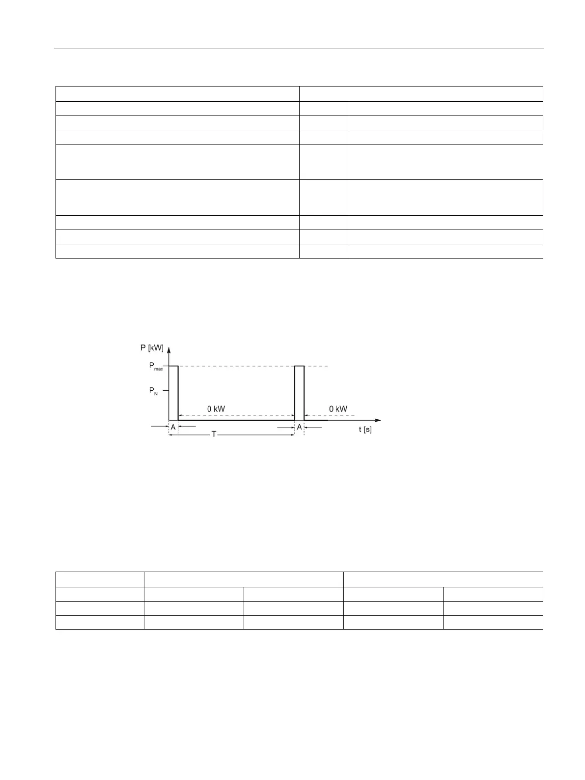
Duty cycle for braking resistors without a thermostatic switch
Figure 8-5 Duty cycle for braking resistors without a thermostatic switch
T [s] time period of braking duty cycle
A [s] load duration
P
N
[kW] rated power (continuous power) of the braking resistor
P
max
[kW] peak power of braking resistor (6 x P
N
)
Table 8- 6 Duty cycles
A [s] 0.1 0.4 1 2
The following applies when connecting Braking Modules in parallel:
P
N total
= 0.9 x total P
N
of single devices
P
max total
= total P
max
of single devices
 Loading...


