Motor-side power components
10.2 Voltage Protection Module VPM
Booksize Power Units
Manual, (GH2), 07/2016, 6SL3097-4AC00-0BP8
577
The signaling interface has the following assignments:
Table 10- 11 Signaling interface X3
Operating message for Control Unit
• The cable shield is connected to the
VPM housing via the cable entry.
• Isolated contact,
current carrying capacity: 30 V DC at
0.1 A
2 Operating voltage +24 V (from exter-
nal source)
Type: WAGO spring-loaded terminal, type 226-111
max. conductor cross-section: 1.5 mm
2
,
shielded cable
Cable gland: Max. 9 mm ∅
Types VPM120, VPM200 and VPM200 Dynamic
• Screwed joint: 1 x M16, e.g. from the Pflitsch company, Article designation: UNI DICHT EMV
2165211S05
• Locknut M16: GM216PA
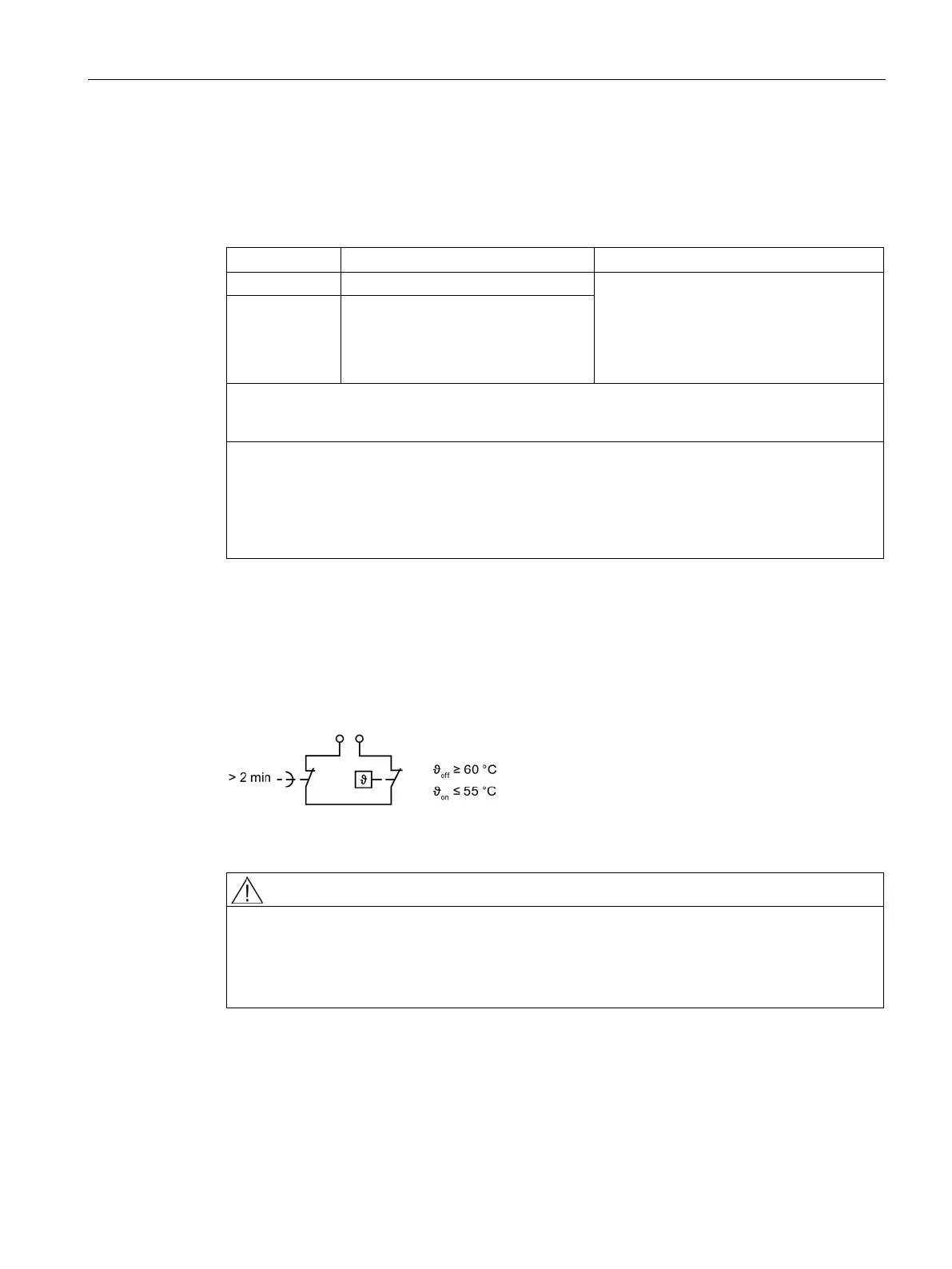
Operating message via signaling contact X3
After a Voltage Protection Module response or in the event of a temperature error, signaling
contact X3 opens and interrupts the inverter system's pulse enable.
The X3 signal contact automatically closes after t > 120 s or after resetting the temperature
switch.
Figure 10-8 Signaling contact X3 of the Voltage Protection Module
Danger to life when the drive automatically starts to run in an uncontrolled fashion
An uncontrolled automatic start of the drive can result in death or severe injury.
• Take measures to prevent the drive starting automatically in an uncontrolled fashion, as
signal contact X3 restores the pulse enable after 2 minutes.
 Loading...


